
This post is part of the industrial IoT series in which we have explained how to digitize an industrial manufacturing process using the balena platform. Digital Transformation is enabling companies to collect data from their connected factories, analyze it, and make real-time decisions. We’ve shown how the ability to update software running on your edge IIoT gateway can significantly empower your business, IT (Information Technology) and OT (Operational Technology) departments. IT is typically part of the visible, front-end business technology managed by the technical department of the company, while OT is mostly software and systems found on the factory floor.
In the first part of this series, we detailed how to use the MING stack in industrial environments and gather data from multiple machines and sensors using Modbus Serial, Modbus TCP or OPC UA, HiveMQ MQTT brokers at the edge, and the MING stack to analyze data at the edge inside the factory.
In the second part, we scaled the edge IIoT gateway solution across multiple factories using the same edge approach, but with a HiveMQ Enterprise Cloud MQTT broker serving as the single source of truth from all connected factories. We introduced the concept of the Unified Namespace (UNS) and utilized vanilla MQTT to connect multiple production lines, modeling the data in the UNS with the ISA-95 and ISA-88 standards.
In this blog post, we are going to enhance the previous solution. Now we are going to use Ignition Edge at the edge IIoT gateways to define the data model, capture the OPC UA and Modbus TCP data, and transmit them over MQTT. Furthermore, we are not going to use vanilla MQTT but instead we will adopt the Sparkplug specification on top of MQTT. The goal is to capitalize on the defined topic structure of the MQTT messages using this open solution, which, despite not being perfect, will help define the payloads. We will continue to use InfluxDB as Historian and Grafana at the edge to enable the IT and OT teams to query data from the edge gateways as-needed. All while utilizing the advantages of the balena platform. In the cloud, we are going to use HiveMQ Cloud Enterprise with Sparkplug topics and the Unified Namespace defined, as well as the Ignition SCADA solution running on balena. Ignition won’t only be subscribed to the HiveMQ Cloud broker and visualize the data, it will also publish calculated data to the Unified Namespace available on the HiveMQ Cloud MQTT broker.
Are you ready to transform your Industrial IoT deployment towards the next stages using balena?
What is Sparkplug?
Before we proceed, let’s introduce some concepts such as Sparkplug and why it is necessary. In vanilla MQTT, which we used in previous episodes, you can publish to any topic and use any data format that you’ve defined for plugging into the Unified Namespace. However, in industrial use cases, you don’t want anything or anyone to publish to just any topic or with any type of payload.
The Sparkplug specification, created by Cirrus Link in 2016, is built on top of the MQTT protocol and doesn’t alter the MQTT specification. Sparkplug provides an open-source and standardized way of structuring MQTT topics and representing payloads sent among devices in an industrial environment to help reduce friction in industrial interoperability. Sparkplug defines an OT-centric topic namespace and a payload definition optimized for industrial processes. Sparkplug also sets the session state management rules required by real-time OT SCADA systems. For instance, a device must publish a Birth Certificate as soon as it joins the MQTT network, announcing the metrics it will be publishing and commands it is capable of executing. You can read the Sparkplug standard definition here.
In the manufacturing use case, you can use DataOps or IIoT tools to build the structure of your Unified Namespace and manually map all events to it for publishing to an MQTT broker using Sparkplug, as we’ll demonstrate below. From that moment, your semantic namespace will be available on your MQTT broker, and you’ll be able to start publishing and consuming MQTT Sparkplug messages under that namespace.
The Sparkplug Topics and Payloads
In a Sparkplug architecture there are usually three main elements: the Edge of Network Node, the Host, and the devices. The Edge of Network Node (EON Node) is responsible for gathering data from the OT level devices, grouping the data and publishing it to the MQTT broker. The Host (also known as Scada IoT Host) are the primary applications that retrieve the data from the EON Nodes via the MQTT broker. Usually the primary application is a SCADA that is part of the Industrial architecture.

The topic definition on Sparkplug follows this semantic namespace:
namespace / group_id / message_type / edge_node_id / [device_id]
The namespace element of the topic namespace defines the structure of the namespace elements; the current Sparkplug definition defines two namespaces. For this project we are going to use the spBv1.0 namespace following the Sparkplug payload definition B. You may recognize Sparkplug as Sparkplug B as it uses this namespace.
The group_id element provides a logical grouping of the Edge of Network node into the MQTT broker.
The message_type is defined on the Sparkplug Topic Namespace standard and it indicates the type of message. For example DDATA stands for Device Data message.
The edge_node_id identifies a unique Edge of Network node. The group_id with the edge_node_id have to be unique from any other node on the MQTT broker, to identify that specific Production Line or similar.
Finally the device_id is an optional element that represents the device connected to the Edge of Network node.
These are examples of a real Sparkplug topic definition:
spBv1.0 / Line1 / DDATA / Line1Gateway / compressor
All of the payload messages on Sparkplug are going to be encoded using protocol buffer (protobuf) and sent compressed as a binary message. The JSON payload on Sparkplug looks like this:
{

"timestamp": 1486144502122,

"metrics": [{

"name": "my metric",

"alias": 1,

"timestamp": 1479123452194,

"dataType": "String",

"value": "Test"

}],

"seq": 2

}
Sparkplug provides a consistent topic naming structure and payload format definition on IIoT and SCADA.
Why is Sparkplug not perfect for ISA-95 data modeling?
You may recall the ISA-95 data modeling for the industrial use case that we described on the previous blogpost here. The project we were working on was modeled through this data object model following the ISA-95 and ISA-88 standards.
Enterprise => HiveMQ_Balena_Enterprise;

    Site => Munich

        Area => Bottling_Area

            Production Line => Line_1

                Work Cell => IIoT_Gateway

                    Equipment_Module => Compressor_1
However the use of Sparkplug to package those edge data objects and publish them together to the MQTT broker scales easily. The alternative is to do it manually without creating a logical network of topics. This provides more flexibility by following the ISA-95 standard (and ISA-88 if needed) to decide how the data is going to be visualized in the Unified Namespace.
The ISA-95 recommendation following the Enterprise / Site / Area / Line / Cell format is not exactly the same as the Sparkplug format with Group ID / Edge Node ID / Device ID. However there are workarounds to use a longer hierarchical representation on Sparkplug. That can be archived by using delimiters on the topic as follows:
spBv1.0 / Enterprise:Site / DDATA / Area:Line / Cell
As an example for the Bottling areas from Munich and Barcelona we might have:
spBv1.0 / Barcelona / DDATA / BottlingArea:Line1 / Compressor1
spBv1.0 / Munich / DDATA / BottlingArea:Line1 / Compressor1
However, this requires you to perform some additional work on the receiving end to identify the delimiters and unpack this to a routable MQTT topic. In addition, some platforms like Ignition allow you to use the name field of the payload to represent a hierarchy, which could be used to extend a hierarchy as shown below:
{

"timestamp": 1486144502122,

"metrics": [{

"name": "Enterprise/Site/Area/Line/Cell",

"alias": 1,

"timestamp": 1479123452194,

"dataType": "String",

"value": "Test"

}],

"seq": 2

}
Why use MQTT Sparkplug?
In this project, we’re implementing an edge industrial data reference architecture with balena and HiveMQ. The unique value lies in the capacity of all the edge elements running on balena to remotely update their software and the operating system. As an evolution of the previous episode’s solution, the addition of Sparkplug offers an enhanced capability for the system to scale using industrial platforms.
An industrial data architecture with Sparkplug necessitates a SCADA IIoT Host as a Primary Application. This Primary Application supervises, monitors, and controls the MQTT Edge of Network Nodes and the connected devices. It manages the state of all the systems within the architecture at any given time.
Typically, a SCADA system serves as the Sparkplug Primary Application, which is why we will use Ignition as the Primary Application. Taking advantage of the Ignition platform, we’ll deploy Ignition Edge on every edge gateway of the Edge of Network Nodes. Instead of letting the SCADA application manage all the connections, we’ll utilize a central MQTT broker via HiveMQ over Sparkplug to handle all the messages in the form of a Unified Namespace.
InfluxDB Sparkplug extension on HiveMQ
In the previous IIoT blogposts, we were sending the data to InfluxDB directly from NodeRED, N3uron or the Data Processing service running on the edge. However in this case we are going to use the HiveMQ extensions to store the data directly from the edge MQTT broker to the time-series database.
As we are using Sparkplug B with MQTT we will install the HiveMQ Sparkplug InfluxDB extension in the HiveMQ service. To manage the extension you will need to configure some device variables through balenaCloud and during the deployment.
The first variables will set up the InfluxDB session. This project is running with InfluxDB 2.7.
DOCKER_INFLUXDB_INIT_MODEwhich is defined assetup.DOCKER_INFLUXDB_INIT_BUCKETwhich is defined asbalena.DOCKER_INFLUXDB_INIT_ORGwhich is defined asbalena.DOCKER_INFLUXDB_INIT_USERNAMEwhich is defined asbalena.DOCKER_INFLUXDB_INIT_PASSWORDwhich is defined asbalenabalena.DOCKER_INFLUXDB_INIT_ADMIN_TOKENwhich is defined as a token generated by Influx. and needs to be the same as the variableHIVEMQ_SPARKPLUG_TOKEN.
These variables will set up the HiveMQ Sparkplug extension that will send the data through InfluxDB, as previously set up.
HIVEMQ_SPARKPLUG_ADDRESSwhich is defined as the name of the influxDB service running. In this caseinflux.HIVEMQ_SPARKPLUG_BUCKETwhich is defined asbalena.HIVEMQ_SPARKPLUG_DATABASEwhich is defined asbalena.HIVEMQ_SPARKPLUG_MODEwhich is defined ascloud.HIVEMQ_SPARKPLUG_ORGANIZATIONwhich is defined asbalena.HIVEMQ_SPARKPLUG_PORTis defined as8086.HIVEMQ_SPARKPLUG_TOKENis defined in the Github repository as an example token.
What is a SCADA system?
SCADA (Supervisory Control And Data Acquisition) is a system for monitoring and controlling industrial processes. It provides real-time data and graphics, assisting operators (from the IT side) to visualize the processes under control and allows the operators to send commands to the plant floor operators (OT side).
As mentioned above, a SCADA system will be necessary as a Primary Application in our architecture if we use Sparkplug. Incorporating SCADA into the architecture introduces a tool that builds industrial visualizations and can send commands to the OT devices and calculate data to be sent to the Unified Namespace.
We have chosen Ignition as the SCADA system for our project. You can find more information in this blogpost about how to deploy Ignition on balena.
Ignition Edge
Ignition Edge brings the power and flexibility of the Inductive Automation Ignition SCADA platform directly to the edge of your factory floor. Designed to run on edge devices such as Raspberry Pis or the latest edge-of-network x86 devices powered by balenaOS, Ignition Edge provides essential capabilities such as OPC UA drivers, a one-week data buffer, two device connections and Gateway Network connections. Although the trial version operates for only two hours, it offers a glimpse of the solution’s potential. For continuous service, a simple restart from the Ignition interface is required when the 2 hours license is expired.
Deploy the Industrial IoT project with balena
In this blog post, we will collect data from the OT level via Ignition Edge, deployed on the IIoT Edge gateway managed by balena. Ignition Edge will accumulate data from the PLCs sending data over Modbus TCP and OPC UA. The data will be packaged into Sparkplug and transmitted via MQTT through the HiveMQ broker at the edge. This edge MQTT broker will use the HiveMQ bridge extension to publish to the HiveMQ enterprise at the cloud level, serving as our Single Source of Truth. The HiveMQ cloud MQTT broker will establish the Unified Namespace and receive all publish and subscription messages from all the company systems. Ultimately, the Ignition SCADA system will be used as the Primary Host for the Sparkplug system and will subscribe to the data modeled through Sparkplug, making it visible through the SCADA interface that you design.
To deploy this project we will need two x86 devices (e.g. Intel NUC or similar devices) and the HiveMQ Cloud solution.

Finally, at the edge, we will still maintain the InfluxDB time series database service as Historian, along with Grafana dashboards. In industrial environments, it’s important to have data stored in at least two places, if possible. Grafana dashboards can help IT and OT personnel to locally query specific data, thereby avoiding inefficient queries to the cloud system from local sites. InfluxDB will be populated directly from the HiveMQ edge broker Influx extension.
On the Cloud Level there is a second balena device running Ignition Enterprise SCADA solution. This second balena device can be hosted in the cloud or in your factory network. It will work as a Primary Application Host and will be able to unify all the data coming from multiple IIoT Edge gateways sent via Sparkplug MQTT through the HiveMQ Enterprise Cloud.
Getting started with the IIoT Edge Gateway
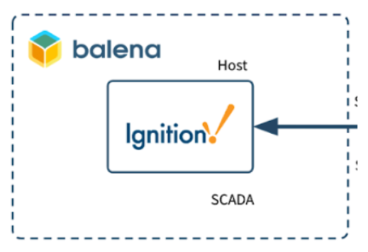
The first device is the IIoT Edge gateway, which is a x86 (amd64) device type available in the edge of multiple shop floors. It will run Ignition Edge, HiveMQ, InfluxDB and Grafana on balena.

You can find the example repository here. The repository’s README file contains all of the necessary details for deploying a few different examples which we’ll outline below.
Deploy with balena
Running this project is as simple as deploying it to a balenaCloud application. You can do it in just one click by using the button below:

Follow instructions, click Add a Device and flash an SD card with that OS image dowloaded from balenaCloud. Enjoy the magic 🌟Over-The-Air🌟!
Getting started with the Ignition SCADA on balena
This balena device will be a x86 device running Ignition Enterprise standard SCADA solution with balenaOS in the cloud or in the company’s data center. This second device will work as a Sparkplug Primary Application Host and will be able to unify all the data coming from multiple IIoT Edge gateways sent via Sparkplug MQTT through the HiveMQ Enterprise Cloud.
You can find the example repository here. The repository’s README file contains all of the necessary details for deploying a few different examples which we’ll outline below.
Deploy with balena
Running this project is as simple as deploying it to a balenaCloud application. You can do it in just one click by using the button below:
Follow instructions, click Add a Device and flash an SD card with that OS image downloaded from balenaCloud. Enjoy the magic 🌟Over-The-Air🌟!
Final thoughts
As seen on the series of Industrial Internet of Things posts published here, you can use multiple variations of software running on the edge with balena. The aim of these guides are to inspire you to start digitalising your industry with the advantage of using balena which will enable you to update the software and manage your edge devices remotely. Expect in the near future more Industrial IoT applications with AI, with new data structures and let us know if you would like to see anything specific running on balena.
Feedback
If you have any issues with the Ignition Edge integration, the HiveMQ Bridge Extensions, MQTT Sparkplug B or others feel free to contact us at the balena forums and share the error logs that you get and as much as details as possible.
The balena platform is all about reducing friction for fleet owners. As always, let us know if you run into any issues when following this guide or getting the Industrial IoT gateway reference architecture set up in your factory or industry plant floor.
Feel free to add a comment below or contact us on the balena forums.
Start the discussion at forums.balena.io