
This is the second of a series of posts about the key features that make the balenaFin the right choice for fleet owners. For all those who are not familiar with the balenaFin, you can take a look at this introductory post. We’ve divided the series into three posts that cover the main categories: storage, power and networking.
This post is focused on power, more specifically, why input power is not the only important factor and the details that make or break a solution when subject to the challenging environment of field deployments.

IoT devices are being used in a wide variety of applications; from farming and manufacturing, to drones, retail, wearables and smart building technology. Each of these applications have very different power requirements in terms of input, connectors, and usage.
For devices used on a factory floor, power is not usually a concern, however, companies use a variety of power supply voltage standards and connectors, presenting a challenge for devices that need to meet the different requirements.
On the other end of the spectrum, we have seen an increase in demand for devices that can be used in power-constrained environments, where they only process information for brief periods of time but remain in a low-power state for the most part. Smart farming is a good example of this, where devices are required to run from a limited energy source (solar panels or batteries) for several months with minimal intervention or no intervention at all.
Building a board with the right power circuitry to support many different applications, in a wide variety of environments was challenging, but we did it. The balenaFin has been designed to provide flexibility for fleet owners to find the power source that best suits their use case. Let’s explore what the balenaFin offers both in terms of power input/output and power usage.
Input/Output power
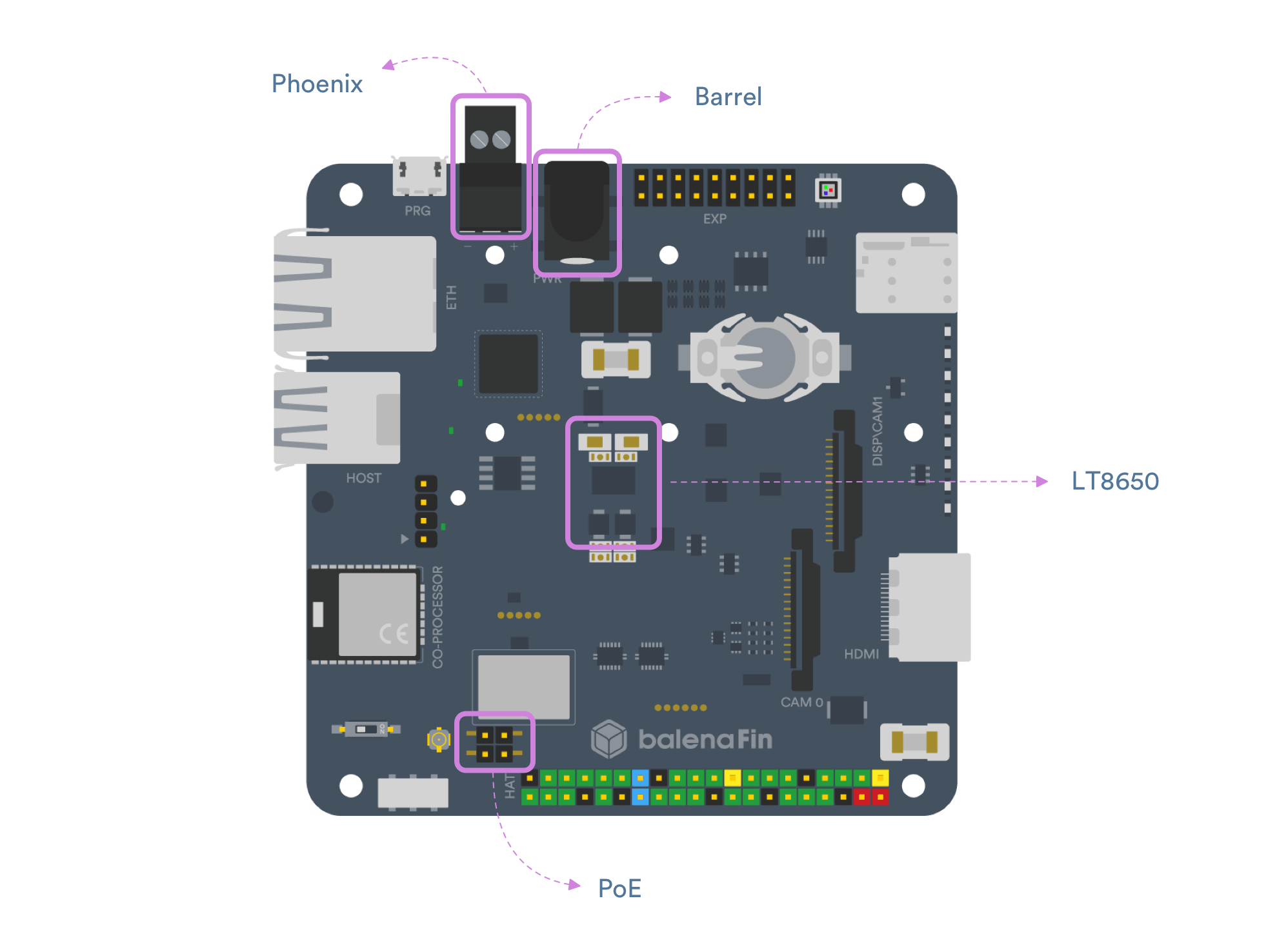
The balenaFin power circuit is based on the LT8650S chip. It’s an Industrial/Automotive grade integrated circuit that provides high-efficiency voltage conversion for improved power usage and low emissions for passing the strictest automotive regulations.
The input voltage range of the balenaFin is 6V-24V. While the overall input range of the LT8650 is 3V-40V, there are some PCB space and heat dissipation constraints that reduce the range on the balenaFin.
This 6V-24V range provides a good deal of flexibility when choosing from different power supplies, since most industry standards fall somewhere in the middle. This includes multi-cell drone batteries, DIN-Rail type power supplies, solar energy systems, some lead-acid batteries, etc.
Most field applications also require the use of external accessories that can take many forms, for example, USB dongles, mini PCI-Express cards, or even custom designed HATs. The high current output (1.5A @ 5V) of the balenaFin power circuit enables many of these accessories to be powered directly from the balenaFin PCB, without the need for external power supplies, which simplifies the design of the final solution.
Input connectors
The balenaFin can be powered through two industry-standard connectors, a 3.5mm terminal block connector, and a 2mm barrel jack connector.
In addition to this, the balenaFin is compatible with Power over Ethernet (PoE) standards. This allows the use of active 802.3af/at PoE via the use of a compatible HAT.
The wide input voltage range of the balenaFin also allows the use of 12/24 passive PoE by taking the power supply from the PoE header and feeding it to the input power circuit via the phoenix connector or barrel jack. It is extremely important to use the right passive PoE voltage and avoid feeding the balenaFin with more than 24V.
Power budgeting
While power usage isn’t much of a concern when powering the system from a mains power supply, it makes a huge difference when targeting battery powered or energy harvesting (ie solar panels, peltier cells, etc) applications.
In most cases, the system is not intended to run at full load for the whole time, but rather required to remain in a low power state and only “wake up” with some external trigger. Common triggers are time-based (eg. the device is required to take a measurement every X amount of time), user-based (eg. the device is required to interact with a user only when it gets close), sensor-based (eg. an external sensor triggers the device to send information to the cloud).
Powerful microprocessors (such as the one on the Raspberry Pi) are usually not very good at saving power, for that reason the balenaFin includes a low-power co-processor (BGM111) that can be used to completely power on and off the Raspberry Pi Compute Module. The co-processor has a substantially lower power usage than the compute module, allowing the balenaFin to run for a longer period of time with less power.
balenaFin power usage
In order to provide a sense of the benefits of having a low-power mode, we run power usage tests in three different scenarios:
- Normal: in what could be a normal operation scenario, we measured power usage when the Compute Module was running a WiFi access point example and the coprocessor was running a BLE scanner example
- Idle: for this scenario, the Compute Module was kept idle (only running the OS) and the coprocessor was running the same BLE scanner example
- Sleep: in this case, the Compute Module was completely shut down (using our Firmata library) and the coprocessor was left idle in the normal operation mode.
| Avg. current | Max. Current | |
|---|---|---|
| Normal | 1.97W [164mA@12V] | 2.94W [245mA@12V] |
| Idle | 1.73W [144mA@12V] | 2.58W [215mA@12V] |
| Sleep | 0.03W [2.5mA@12V] | 0.047W [3.9mA@12V] |
While the two higher power modes (“normal” and “idle”) are comparable with a regular Raspberry Pi 3B+ under similar conditions, the sleep mode offers a substantially better performance in terms of power usage.
It is important to notice that neither of these cases are extreme ones. It is possible to achieve lower power usage by putting the co-processor in a sleep mode or by shutting down the status LEDs for example. It is also possible to achieve higher power usage by running a more demanding radio application or by using some of the other available peripherals (Ethernet, HDMI, etc).
Note: all tests were run under the conditions below.
- Power supply: 12V PSU
- Operating System: balenaOS
- Current measurement circuit: µCurrent
How to select the right battery/solar panel?
Finding the optimal battery (or battery and solar panel combination) ultimately needs to be tested on the field since many factors can affect the performance (eg. ambient temperature, available sunlight, dust accumulation, battery degradation, etc).
Here are some things to keep in mind when selecting a battery and solar panel.
- Identify the power requirements of your system, this means what’s the power usage at the low-power and high-power states. You can use the table above to get an idea of what a low-power and high-power state looks like.
- Find what the average power usage is, in other words, how much time the system spends in each state.
- The battery size will depend on how long you expect the system to run without energy from the solar panel. For example, if the average usage is 100mA and you want the system to be able to run for a whole week (168 hours), the battery will need to be 16,800mAh (roughly a small-sized smartphone power bank).
- For the solar panel, a good starting point is to target a full recharge of the battery every 24 hours. Continuing the example above, the system would use 2400mAh (100mA in 24 hours) in a day. Assuming an 8 hours sunlight availability, we would be needing a 300mA (2400mAh in 8 hours)* solar panel. This translates into a 1.8W panel if the voltage is 6V.
*This is a somewhat optimistic scenario, considering that the solar panel won’t be providing 100% of the power during the 8 hours and that there will be a loss on the battery charging circuitry.
In many cases the solar panel voltage needs to be converted to a lower voltage to be fed into the system, introducing more power loss. That’s also another case where the high input voltage of the balenaFin comes in handy to avoid the need of converting the power.
Of course, all these assumptions can be more aggressive or conservative depending on the use case. The best approach is usually to run a conservative scenario and put the system out in the field. Once the real data comes in, you can scale down the requirements until you find the optimum solution.
Final thoughts
When designing connected devices intended to be deployed at scale in the field, fleet owners face challenging power constraints. The balenaFin has been designed to offer a reliable power management while keeping a high degree of flexibility in compatible power input sources, both in terms of voltage and power usage.
Here’s a quick summary of the key points discussed:
- Input voltage range: 6V-24V (12.5W)
- Output current: 1.5A @ 5V
- 2mm barrel jack connector
- 3.5mm terminal block Phoenix connector
- Standard 802.3af/at PoE capable (via external HAT)
- 24V passive PoE capable without external HAT
- Low power mode via the coprocessor
If you are interested in the balenaFin, head over to our store and get yours. Feel free to reach out to us to [email protected] for any questions regarding the balenaFin.
