This is the first of a series of posts about the key features that make the balenaFin the right choice for fleet owners. For all those who are not familiar with the balenaFin, you can take a look at this introductory post. We’ve divided the series into three posts that cover the main categories: storage, power and networking.
In this post we’re going to look specifically at the points to consider when choosing a storage solution for the balenaFin, the design choices we made and the reasoning behind those choices.

Selecting the right kind of storage for an Internet of Things (IoT) application requires balancing several requirements that often conflict with each other (size, read/write speed, temperature range, vibration resistance, longevity, price, availability at scale, etc.).
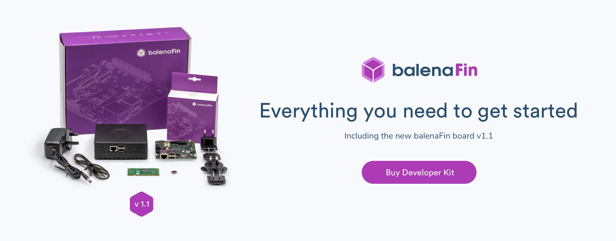
The balenaFin was designed with IoT field applications in mind, where the use of a reliable storage method that can perform in a whole range of different environments is key. Storage on the balenaFin is based on an industrial grade eMMC memory chip with 8GB, 16GB, 32GB and 64GB options available.
We settled for this particular memory chip after evaluating the performance of different flash based storage solutions in three main categories; speed, environment, and endurance.

Speed
While SSDs have the fastest read/write speeds flash storage can provide, its high cost and the Raspberry Pi Compute Module’s (CM3) lack of a fast mass storage bus makes it a less than ideal choice for the balenaFin.
eMMC speeds are substantially higher than SD cards and the protocol is natively supported by the Compute Module, meaning no additional components are required to provide the interface.
Below is a quick comparison between the typical SD card used on a Raspberry Pi 3B+/ RPi4, the on board eMMC of non-Lite CM3 and the eMMC on the balenaFin:
| RPi 3b+/RPi 4 | RPi CM3 (non-Lite) | Balena Fin | |
|---|---|---|---|
| Type (Vcc 5V) | Micro SD | eMMC | Industrial grade eMMC |
| Sequential read/write performance | Up to 90/80 MB/s | Up to 250/100 MB/s | Up to 300/170 MB/s |
| Capacity | 8GB – 128GB | 8GB – 32GB | 8GB – 64GB |
| Storage Management System | Host-side Flash File System | Built-in controller | Built-in controller |
The high speed of the storage used on the balenaFin not only improves the general performance of the device but also means that the use of swap space on disk is now practical. This means you can provide more memory to your application processes, circumventing the 1GB memory limitation of the Raspberry Pi Compute Module and allowing fleet owners to deploy a wider variety of applications.
Low-power applications
These are scenarios where the main processor is active a couple of seconds at a time, which can also benefit from reduced boot and execution times. This translates into lower overall power consumption.
Environment
IoT systems are deployed in tough environments, where vibrations, electromagnetic noise, and extreme temperatures are usual. There are several advantages of eMMC memories over their SD card counterparts:
- eMMC cards are soldered to the board, making them an optimal solution for high-vibration environments such as moving vehicles, drones or industrial machinery.
- Along the same lines, eMMCs cannot be easily removed from the board, which adds an extra layer of security for the information contained in them.
- The eMMC on the balenaFin has been tested against conditions like power fluctuation and electromagnetic interference and proven to withstand demanding environments.
- Wide temperature range flash memories can be found in almost all formats. For the balenaFin we selected a -25°C – 85°C range memory, which is actually higher than the limit set by the Raspberry Pi Compute Module 3 Lite of -25°C – 80°C.
The increased tolerance of the storage medium toward a variety of environmental factors allows fleet owners to deploy the balenaFin in a much wider variety of locations than is feasible with other devices. This is particularly true for outdoor deployed devices and drones, where vibrations and extreme temperatures push IoT devices to their limit.
Endurance
Due to the physical construction of flash memories, there is a limited number of times each cell can be written. This limitation is usually specified in program/erase cycles (P/E cycles), which represents the number of times a single cell can be programmed (written or erased).
These blocks can only be programmed in groups called blocks. This means that every time a byte is to be programmed, the whole block is, which causes the block to lose a P/E cycle.
The eMMC in the balenaFin has a built-in wear leveling algorithm, which distributes the load across the whole memory. This prevents data from being programmed in the same memory blocks and avoids premature wear of those blocks.
With a rating of up to 3000 P/E cycles, the balenaFin eMMC sits at the top end of regular flash memory architectures (MLC). While it is possible to use a higher endurance flash architecture (called SLC), these are usually an order of magnitude more expensive, making them hard to budget for an IoT application.
Estimating the lifetime of the balenaFin memory
The actual duration of an eMMC memory in a real life application also depends on a number of factors particular to such application: write/erase frequency, size of each write operation, average free space on the memory, etc.
In order to calculate the memory lifetime of the balenaFin eMMC, let’s assume that our application writes 160MB of data per day on a 16GB balenaFin. The actual lifetime of the eMMC will depend a lot on how those 16MB are written.
Since the P/E cycles on the balena is 3000, we can write each block 3000 times so the total “lifetime” memory is 16GB x 3000 which equals 48,000 GB. The block size on the balenaFin is 4MB.
The optimistic scenario
If the 160MB are written in 4MB blocks (40 x 4MB blocks), then:
Write amplification = write_size / block_size = 4MB / 4MB = 1
Lifetime = lifetime_memory / (daily_data * write_amplification) = 307,200 days (841 years)
The pessimistic scenario
If the 160MB are written in 4KByte blocks, then:
Write amplification = write_size / block_size = 4MB / 4KB = 1024
Lifetime = lifetime_memory / (daily_data * write_amplification) ~= 300 days (1 year)
Any real application will be in the middle of those two scenarios, considering that the operating system also uses the storage and in most cases is very difficult to achieve a constant data block.
Recommendations to improve eMMC lifetime
Here are some general guidelines that help achieve a longer lifetime for flash-based storage systems and in particular the eMMC on the balenaFin.
- Consider using flash-optimized operating systems. The balenaOS team has done an incredible job at buffering logs on RAM before writing to flash to avoid wear.
- When writing to memory, use chunks of data with a size as close as possible to the erase block size (4MB for the balenaFin). This optimizes the amounts of P/E cycles required for each operation.
- Select a larger eMMC storage than what the application demands. This allows the wear leveling algorithms to distribute the load across more memory blocks, thus decreasing the amount of P/E cycles each block has to sustain.
The superior endurance of the eMMC-based storage on the balenaFin allows fleet owners to deploy the board with a level of confidence far greater than that found when using SD card based storage methods.
Final thoughts
Weighing the advantages and disadvantages of each storage type we found eMMC memories to have the best balance between cost, speed, endurance and environment protections for an IoT application. With hundreds of balenaFins deployed in the field, we were able to test the storage performance in a wide variety of applications with very positive feedback.
Here’s a quick summary of the key points:
- Storage type: Industrial grade eMMC
- Read/Write performance: 300/170 MB/s
- Capacity: 8GB – 64GB
- Temperature range: -25°C – 85°C
- Vibration and tamper resistant by being soldered to the board
- Tested against power fluctuations and EMI (electromagnetic interference)
- Endurance: 3.000 program/erase cycles
Hope you enjoyed the first post of this series, we’ll follow up with more information about networking and power input in the next posts. If you are interested in the balenaFin, head over to our store and get yours. Feel free to reach out to us to [email protected] for any questions regarding the balenaFin.