

Earlier today, we announced our decision to recall all v1.1 balenaFins due to a USB malfunction at high temperatures. If you think your balenaFin might be affected, please follow the instructions outlined here.
This issue prevents affected balenaFins from accessing any USB peripherals when the ambient temperature rises above 45-50°C (113-132°F). It also means that those devices relying on ethernet connectivity are disconnected at these higher temperatures since the ethernet bridge is also USB-based. The mPCIe connector, being USB-based, will also be affected by the disconnection.
Based on our estimates, around 90% of all deployed balenaFins are likely affected by this issue. We are fully aware that a recall negatively impacts our customers and introduces friction in their fleet operations, which we, as a company, strive to reduce.
Ultimately, it is our responsibility to take this as a learning opportunity to improve our processes. We now have a more robust testing procedure for both our design and manufacturing processes. The performance of every connectivity protocol at low and high operational temperatures is now part of our standard suite of tests.
This blogpost aims to offer an in-depth technical explanation of the underlying issue and the steps we are taking to prevent this from happening again.
balenaFin USB topology

Key components of the balenaFin’s USB topology are presented in figure 1. The two main blocks are the USB hub and switch, which allows for regular USB operation and internal eMMC flashing.
The USB hub is based on the LAN9514i chipset (LAN9514 on the v1.0 revision), which has an integrated USB to Ethernet bridge (PHY included). This structure has the benefit of a considerably smaller footprint, but it also means that if the hub is disconnected, so will the Ethernet connection.
The USB switch works by sensing power (VBUS) on the micro-USB connector. When a powered device is detected, the USB interface on the compute module is wired directly to the micro-USB connector. When no powered device is detected, the compute module is connected to the USB hub. The former situation only occurs when the balenaFin is connected to a host device (PC or laptop) to flash the internal eMMC memory.
Reported issues
The first report of a potential operating temperature issue was posted in our forums in June 2019:
We concluded that the USB power protections were being triggered by the heat generated from a combination of high current draw and CPU load. This theory seemed to be confirmed by the fact that placing a heatsink on top of the USB protection chips made the issue disappear.
In retrospect, we missed that the addition of vents also reduced the ambient temperature inside the case, hinting that something else might have been going on.
Approximately a year later, another balenaFin customer contacted us via our balenaCloud support chat to report a similar issue. The following situation was also reported in our forums around that time:
With the help of a customer who performed an extensive early investigation, we extracted two previously unknown facts:
- The Ethernet interface was being disconnected along with the plugged USB devices.
- balenaFin revision (v1.0) did not appear to be affected.
With this new information, we decided to launch a full investigation to test the v1.1 balenaFin’s performance at higher temperatures.
While the v1.0 balenaFin was fully tested under high temperatures, the v1.1 balenaFin was only subject to a limited test suite (cold-boot and power-cycle). There were two main reasons for that:
- Since the LAN9514i hub is individually tested for performance at high temperatures by the manufacturer, we decided to skip this test.
- The only other change related to the USB circuitry was the ability to power from the micro-USB port. This is only used when flashing the balenaFin memory, and not intended to be done at high temperatures.
Investigation
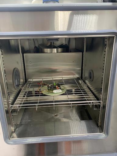
We performed a series of tests in a temperature-controlled chamber that was set to reach an ambient temperature of 80°C, heating at a rate of 1°C/minute. Once the maximum temperature was reached, the devices were left idle for a minimum of 30 minutes before performing any further operations.
July 6th
Test #1:
- Device: Standard v1.0 balenaFin.
- Result: No issues were found on the USB subsystem and no functional degradation was observed.
Test #2:
- Device: Standard v1.1 Fin.
- Result: At 48C ambient temperature, the USB peripherals connected were suddenly shut down. Ethernet connectivity was also lost.
- Observations: Kernel logs reported that the USB hub was disconnected and no longer accessible.
Note: the above tests were repeated in every session with the exact same results.
Test #3:
- Device: Modified v1.1 balenaFin with the USB power controllers removed.
- Results: We experienced the same issues as the unmodified v1.1 balenaFin.
- Observations: This test’s objective was to review our original hypothesis that the USB power controllers are the root cause of the issue. The result disproved our initial hypothesis.
July 10th
Test #1:
- Device: Modified v1.1 balenaFin with the following changes:
- The USB header pins were removed, as this was a significant design change between revisions v1.0 and v1.1 and therefore stood out as a potential culprit
- Wire soldered to the 5V USB bus and connected to an oscilloscope.
- Wire soldered to the 3.3V rail and hooked to an oscilloscope.
- Result: Same as unmodified v1.1 balenaFin.
- Observations: On the oscilloscope, we noticed some noise on the 3.3V rail right when the USB hub was shutting down. This noise suggested a potential issue between the power converters and the USB hub. After the device was power cycled at a constant temperature of 60C, the same glitches were observed every 2-3 seconds.
Test #2:
- Device: The balenaFin from test #1 was modified to cut power to the USB hub by desoldering L20.
- Result: Power glitches were not observed. The USB hub was not powered so it remained disconnected throughout the entire test.
- Observations: Results seemed to point to a power delivery issue at high temperatures. For further testing, we requested our contract manufacturer to produce a v1.1 balenaFin with a LAN9514 (instead of a LAN9514i) to rule out the potential of the issue being caused by a faulty batch of USB hubs. Since the power delivery circuitry stayed mostly unchanged between revisions v1.0 and v1.1, it would also help us single out any power distribution faults.
July 15th
During the previous testing sessions, we were able to consistently reproduce the issue at 45-50°C, allowing us to run tests locally without a professional heat chamber.
We proceeded to test an off-the-shelf v1.1 balenaFin with the LAN9514i replaced by a LAN9514. The results were mainly the same as previous tests, where the USB hub shut down at ~50°C, and the same noise was present in the power rails.
To rule out power delivery being the root cause, we decided to power the USB hub from a separate bench power supply unit placed away from the heat source. Issues persisted with this setup, pointing us away from a power delivery problem.
During these last few tests, we realized that the hub would remain off if it did not receive any signal from the compute module, regardless if it was powered or not. The latter suggested that the issue might not be the hub powering off, but instead not receiving any input from the CM.
Root cause analysis
The issue was introduced by a seemingly unrelated change in revision v1.1 that allowed the balenaFin to be powered from the micro-USB port.

We used Schottky diodes to prevent back current being injected into a power supply in the accidental case where more than one power supply was connected.
This type of diodes is widely used in power applications due to their relatively high forward current and low voltage drop. On the flip side, they typically have high reverse leakage current, which increases by an order of magnitude for every 25°C increase.
Reverse current is hardly ever an issue when sunk by power supplies, even at high temperatures, but in our case, it was causing another undesirable side effect. As shown in figure 3, the USB switch senses the voltage on the micro-USB bus (5V_USB_DBG), and it is triggered when the transistor’s gate voltage (Vg) reaches the transistor’s on level (typically 0.8V).

For the sake of simplicity, the transistor gate current (Ig) can be considered zero, as its value is orders of magnitude lower than the reverse leakage current (Irl). At room temperature (25°C) the value of Irl is around 2uA, making the gate voltage:
plaintext

Vg = Irl * R = 2.5uA * 47kOhm = 117.5mV
At 50°C, Irl becomes 20uA, so:
plaintext

Vg = Irl * R = 203uA * 47kOhm = 940mV
At this temperature level, the gate voltage becomes high enough to turn the transistor on, tying the switch pin to ground and consequently disconnecting the USB hub from the compute module.
Fix
The most straightforward way to reduce the impact of the leakage current in the circuit is to reduce the value of R116 (see image 3). Such value should be low enough such that Vg never reaches 0.6V (which is the minimum ‘on’ voltage according to the transistor datasheet).
There is a small downside to this approach; it will consume more power when the USB switch is on. Such a situation only happens when the balenaFin is put in mass storage device mode to flash the eMMC (powered by the micro-USB connector). In this case, the vast majority of the peripherals are off, minimizing the downside of a slightly larger current, so we decided this was an acceptable tradeoff.
We selected a value of 1kOhm, which makes the gate voltage:
plaintext

Vg = Irl * R = 2uA *1kOhm = 2mV @ 25°C
plaintext

Vg = Irl * R = 20uA *1kOhm = 20mV @ 50°C
plaintext

Vg = Irl * R = 200uA *1kOhm = 200mV @ 75°C
July 27th
We went back to the lab to perform some tests on a pair of fixed v1.1 balenaFins. The test was as follows:
- We ramped the ambient temperature up to 80°C at 1°C/minute.
- We left the boards at the maximum temperature for 3 hours.
- The boards were power-cycled a minimum of four times to discard issues at boot.
- The chamber was cooled down to room temperature, and the boards were power cycled another four times.
- We plugged another set of USB peripherals that were connected to each fin and repeated the above procedure.
We were able to verify that the issue was resolved, and the USB interface remained completely functional throughout the entire process.
Implementing the fix
After the fix was validated, we focused on implementing a pipeline to fix all the v1.1 balenaFins we had in stock. These are the steps we took to guarantee the units were correctly modified:
- A new hardware revision was released (v1.1.1) to track the resistor value change.
- We released documentation to support our contract manufacturer’s workers during the fixing process.
- We installed a controlled high-temperature chamber to test newly fixed units.
- Our quality controlled rigs were updated to perform random high-temperature tests in ~5% of the units.
Lessons learned
After this issue was reported and the subsequent investigation, we substantially improved our design and QA process. Starting from the next revision, we’ve added the following tests to the suite:
Design phase
- Before the final release, the new revision will be tested in a professional temperature test chamber up to 75C for a minimum of 24 hours.
- During those 24 hours, the units will be monitored for :
- CPU performance under stress load
- USB performance
- Ethernet and WiFi connectivity
- eMMC I/O performance
- RTC and battery
- Cold boot and power-cycle.
Manufacturing phase
- A subset (5%) of every manufacturing batch will be temperature tested up to 70C in our QA facilities. The following output will be monitored:
- CPU performance under standard load
- USB connectivity
- Ethernet and WiFi connectivity
- Power-cycle
We are committed to continue learning and improving our hardware design and manufacturing processes. Having many customers using our products in the widest variety of scenarios is what will make the balenaFin a better product in the long run.