
In 2017, we (balena) embarked on a mission to build the ultimate flashing media. As a software company, we didn’t realize the hornet’s nest that we had stepped into. Little did we anticipate that in the process, we would end up re-examining the wheel at every step, going through eight design iterations and creating our own board from scratch. Nor did we expect it to take a full two years — four times our estimate! — for us to have a production-ready device.
It’s fair to say our experience validated that hardware is, well, hard. But we also learnt that with some creativity, patience and a lot of persistence, you can vastly reduce your costs and optimize your product’s UX and design if you’re willing to look beyond standard approaches and take a hard look at each step of the process.
As we await regulatory approval, we can say that despite the delays and multiple setbacks, the journey has been incredibly rewarding, and the result (EtcherPro) equally so. And for those interested in their own hardware challenge, we thought we’d share our story and findings below.
Before we start…
… some context is in order (Skip this section if you are already familiar with Etcher).
Software is the core focus of our company balena. Formerly known as resin.io, we developed balenaCloud, a platform to build and manage fleets of IoT devices — essentially removing friction when dealing with remote fleets (over-the-air updates, multicontainer application, etc).
As balenaCloud gained traction, one onboarding hurdle kept cropping up: people were struggling to flash OS images onto their chosen hardware platform.
Say you wanted to use a Raspberry Pi. You’d first need to use your terminal or some clunky software to download the desired OS image and flash it onto a micro SD card. Every OS had different software, forcing us to keep refining instructions, and none of the tools validated whether the write was done correctly. Next, you’d have to plug the SD card back into the Raspberry Pi and boot the system.
It might sound simple but the process was so tedious, slow and error-prone that it discouraged a good number of our potential users.
~~Frustration~~ Necessity is the mother of invention and so we took the bull by the horns and made our own (open source) image writing application, Etcher, focused on user experience and speed. What we didn’t know was that the problem extended far beyond our use case. As a result, Etcher now has a large community of users, supporters and advocates, flashes about a million images per month and is recommended as the go-to tool by the Raspberry Pi Foundation, Ubuntu, Linux Mint, among others.
Why EtcherPro?
We now had a slick image writer, but what happens when you scale your fleet? Etcher can flash multiple cards simultaneously, but the process still requires a custom USB hub with SD card adapters, which severely impacts your flashing speed. As for the available industrial solutions, the consistent feedback from our users is that these are expensive, slow and clunky — everything Etcher is not. Further, none of these legacy duplicators support Etcher’s ability to flash devices without an SD card.
The writing was on the wall: it became clear to us that if we wanted to help our customers scale their IoT fleets, we needed to build a hardware version of Etcher for professionals — EtcherPro. What we didn’t know was how difficult this would be!
Getting Started: Define the manifesto
From the get-go, our aim with EtcherPro has been to build a duplicator that is fundamentally superior to the alternatives. For this, it was important to define the product’s key distinctions:
- All-in-one: Juggling separate SKUs for SDs, microSDs and USB flash drives is a pain, and unwarranted. A single tool should do it all, including flashing devices directly.
- Extensible: People should be able to extend their rig over time, rather than having to choose the number of devices they need to flash from the start.
- Robust: Etcher’s algorithms have been tuned over millions of flash sessions, with every iteration bringing more user feedback. We’re bringing Etcher’s algorithms to EtcherPro.
- User-friendly: The industrial solutions’ standard design is outdated and has poor ergonomics. We wanted EtcherPro to have a form factor that won’t hurt to use, with a touch screen for richer interactions and features.
- Connected: Current solutions require you to copy your image to a USB stick to feed it to the duplicator. EtcherPro should be able to stream it directly from the network.
- Fast. Like, really fast: Current duplicators advertise speeds of up to 33MB/s. We saw a path to flashing at double those speeds. In practice, we can probably even quadruple those speeds if the medium supports it.
- Automatic updates: We constantly improve Etcher, and we want to bring that experience to EtcherPro. As it happens, we know just the platform to use for the job – balenaCloud.
- Affordable: 1-to-15 duplicators will set you back at least $1,300 and often far more. Our target was to make EtcherPro be profitable for less than $1,000.
Phase 01: What should it look like?
Having defined the key values and intentions of the product we started thinking about how this device could look like. What form factor should we go for and what hardware should we use.
As hardware newbies — our only hardware experience at the start of this project consisted of doing some prototypes for a board, the balenaFin — our first thought was to use off-the-shelf components that we’d carefully arrange in a case. By using tested and proven hardware the idea was that we could reach our goal faster, with minimal risk.
The initial setup therefore consisted of 16 SD card adapters plugged into four USB hubs, plus another four directly exposed USB hubs, all connected to a Rock960 dev board, with a 7in touch display managing the UI.

Off-the-shelf components
As for the look of the casing, we imagined a rectangular shape for the card slots attached to a wedge where the screen would be. This wedge would slide under another EtcherPro device when stacked, leaving only the slots exposed. The shape of the case quickly evolved into just a wedge for simplicity while retaining all the other features.
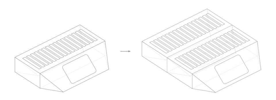
Initial stackable & daisy-chainable concept

First 3D study
During this process, we found ourselves needing a way to provision single-board computers (like balenaFin) in batches. It dawned on us that EtcherPro could be the perfect tool for this. The only thing we needed hardware-wise was an adaptor/ holder to keep the boards and the cables organised.
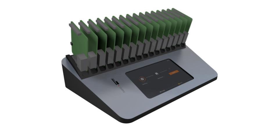
3D study with Fin adapter
Phase 02: How can we manufacture it?
We knew what we wanted it to look like — now, how should we build it?
With little manufacturing knowledge, we turned to our trusted old friend: 3D printing. We’d used 3D printing extensively in our maker projects and figured it was an ideal prototyping tool: it offers relative design freedom, is fairly cheap and you don’t need to commit to molds. Unfortunately, this avenue hit a snag fairly fast. The size of our case meant long printing hours and consequently high costs.
A more rudimentary method proved more successful: cardboard. A handful of cardboard prototypes helped us wrap our minds around the design and understand the constraints we faced.
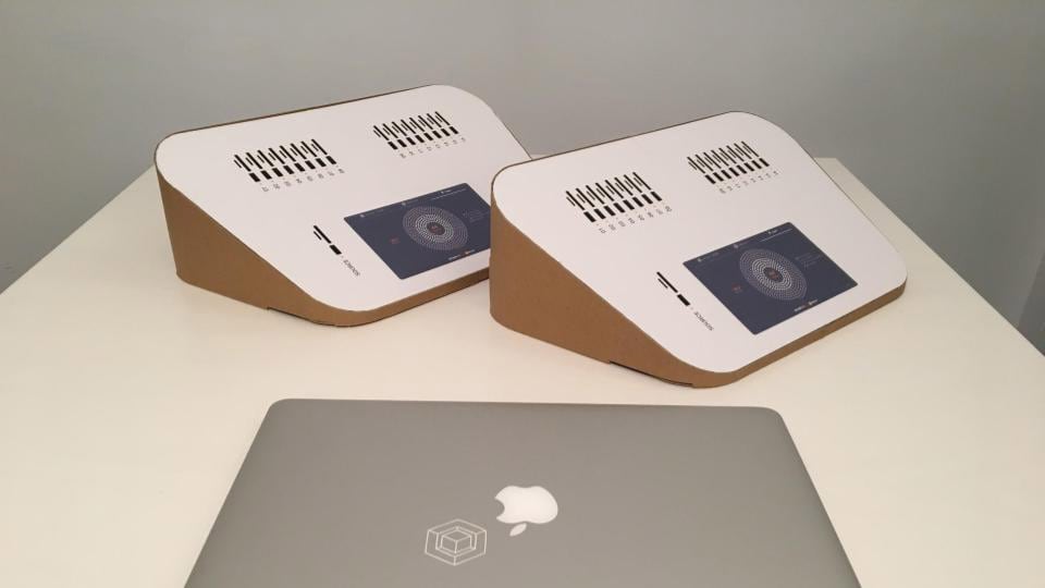
Cardboard prototypes
Next, we started reading up on how to make large cases inexpensively at scale.
Our research quickly pointed us to sheet metal. Using a bent sheet of metal is a ubiquitous method in hardware — think computers, hard drives and even fridge enclosures.
Sheet metal looked ideal to provide a sturdy chassis for our casing’s vertical surfaces. We could then use laser-cut acrylic sheets for the other surfaces, where we could cut and engrave all the details. Theoretically, this method would be very cheap as sheet metal requires no molds (only some cheap jigs) and acrylic cutting is very fast.
Daisy-chaining study
Sheet metal & acrylic study
Unfortunately, this was a blind alley. Long story short, consistently bending metal with large rounded corners is extremely tricky, if not impossible, and the result was a steampunk looking prototype with no dimensional accuracy.
At this point, there were two logical paths ahead. Either constrain the design to fit sheet metal’s requirements — in our case swapping our rounded corners for sharp ones — or change the production materials. Enter silicone.
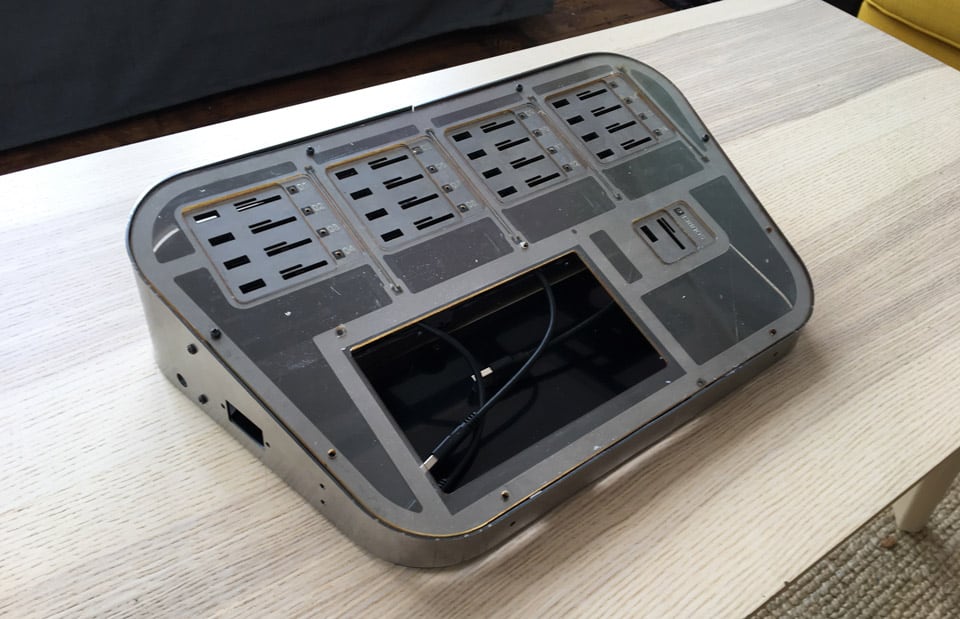
Sheet metal & acrylic prototype
Phase 03: The silicone experiment
Most plastic products you’ll see around you are made using injection molding, whereby plastic pellets are heated and injected into a cavity created by two or more metal molds. This is a great technique, but the metal molds are so expensive that you need huge scale to be profitable. Turns out, silicone molding offers a good alternative: it shares pretty much the same philosophy as injection molding, but silicone molds cost a fraction of their metal counterparts. Silicone’s flexibility also allows for fewer demolding restrictions and in turn greater design freedom.
But then, silicone molding was not new to us. We used it in our balenaFin project as a way to produce cases quickly to fulfil demand while readying our metal injection molds. The result was good enough to make us want to test it out for EtcherPro.
Silicone molding study
But we met a wall here again as it became clear that silicone molding fails at scale. The molds start to lose accuracy after about 100 pieces, and the process itself is slow as demolding is subject to resin’s curing time (as opposed to plastic forced cooling in injection molding). All this pushes up the cost per case quite significantly, defeating our goal of making an affordable duplicator.
Silicone molding prototype
Phase 04: Let’s go custom
As we returned to the drawing board, we realized that our off-the-shelf approach wasn’t going to work. Building cheaply using ready-made hardware and internal cable management would only be possible if we compromised on specifications and appearance. It simply collided with our manifesto on too many fronts.
Around that same time, our balenaFin board was ready to be released. Making the board had substantially boosted our hardware skills and also meant we now had key relationships with manufacturers and suppliers. Most importantly, our first steps into the world of hardware were going well and we felt confident to dive deeper into the EtcherPro project.
And so we did.
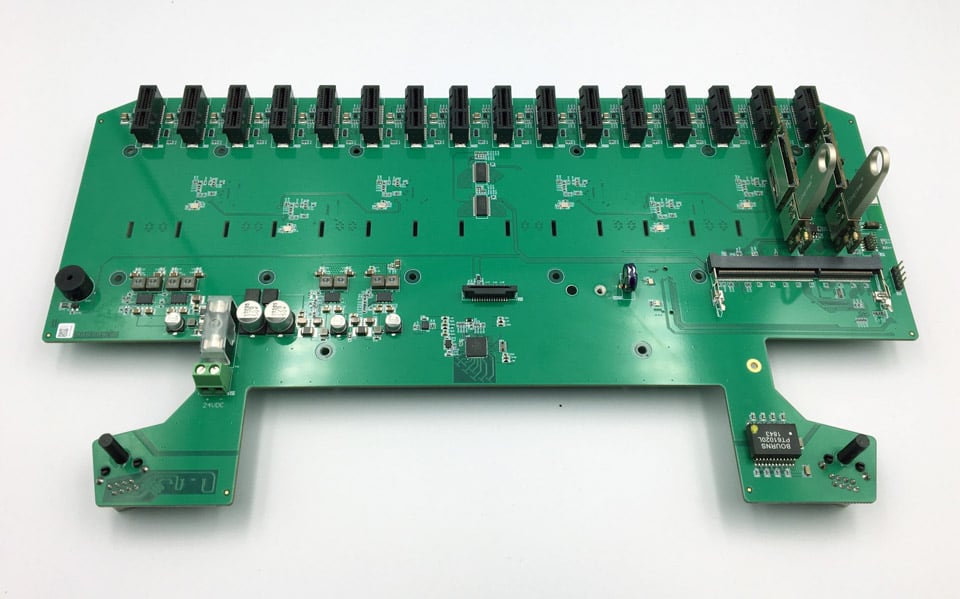
First up, we replaced the hubs with a large custom PCB (daughterboard) that provided all the necessary interfaces either to expose USB ports directly or plug ready-made SD card adapters — a component we retained from the previous phase. You can picture the daughterboard as a large USB hub with ports arranged in a particular order. In addition, the Rock960 was replaced by a more powerful Intel UP2 board, connected via USB 3.0 to our new PCB.
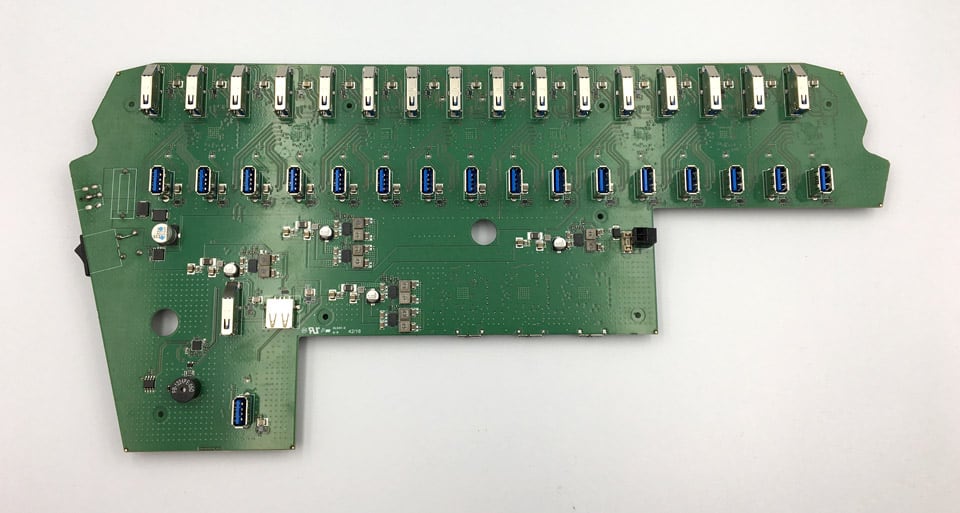
Custom daughterboard
The new PCB was a big improvement and solved many of our problems. The biggest advantage was that it unified the hubs and the card readers into one body that could be mounted with a couple of screws.
We were satisfied that our new PCB opened up new possibilities. But we were still facing major issues on fundamental components and found ourselves unable to scale due to hardware and enclosure issues.
Phase 05: Are we on the right track?
So here we were, with the project ground to a halt once more. As we gathered at our annual company summit in the fall of 2018, we went back to the drawing board and drew out a plan with a renewed focus on our desired outcome and key points. The project was up and running again.
One issue we faced was with the Intel UP2. The board is a beast in performance but also in size. Its huge heat sink was causing issues to our design — it barely fit in our case — while posing critical heat dissipation threats.
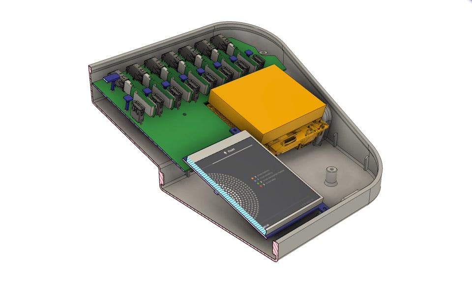
Intel UP2 (yellow) – cross section
The solution we came up with was to modify our PCB design to carry an iMX8 system on module. The beauty of this solution was that it replaced the Intel UP2 altogether. In one fell swoop, we had erased the design constraints and assembly complications that the board had posed. For instance, the UP2 needed special pillars for fastening it, and required that a few cables be routed to the daughterboard. The iMX8 in contrast is just a small card that plugs into the main PCB.
Redesigned PCB
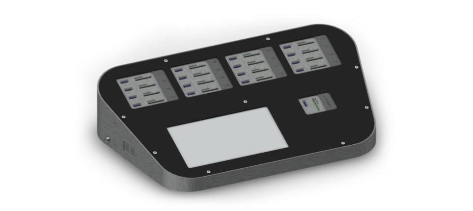
The ready-made SD card readers’ shape required complicated solutions to be fastened. And while their performance was good enough we thought we could do better.
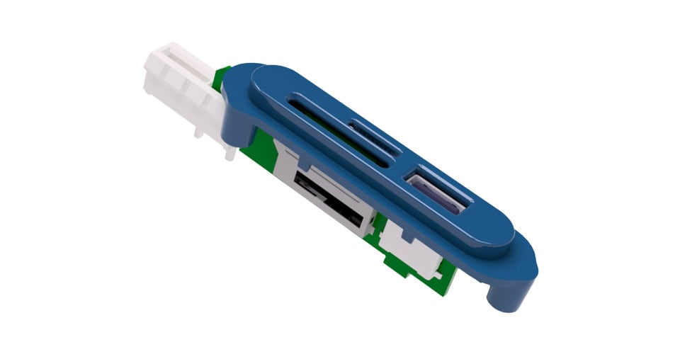
Here again, the answer lied in a custom solution. We decided to design a dedicated card reader to carry all the necessary slots: SD, microSD and USB. This allowed us to position the slots in the desired orientation in relation to each other but also in relation to the top surface. We also moved the LED — used to indicate the state of the flashing process per slot — from the main PCB to the top of the card adapter, removing the need for a light guide.
The custom card reader went against our mission in one way: it increased our production cost. But the improvements we got in speed and part fitting were so substantial that we felt it was warranted.

Custom card readers
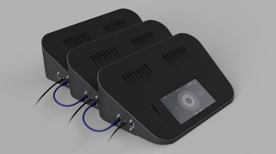
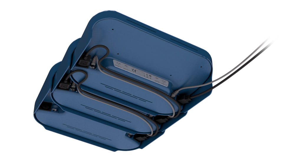
Nailing the daisy-chaining presented a third challenge. Our initial solution — using ethernet cables fixed to the right side of the device — was unsatisfactory. For one, it wasn’t aesthetically pleasing. It also led to a messy cable situation as each device was powered through an external 24V DC power supply meaning a multi-socket lead would be needed when chaining.
Moving away from ethernet didn’t seem possible. We explored a couple of alternatives such as USB 3.0 and WiFi chaining but gigabit ethernet came out as the most straightforward approach. So instead, we focused on solving the power cable mess. After a few iterations, we ended up moving the power supply inside the device and providing a 220v AC input and output. This way, only the first device would need to be plugged in, while the rest of the devices would be powered up by each other. We then also moved the power and ethernet interfaces to the back of the device, which further reduced the cable mess when chaining.
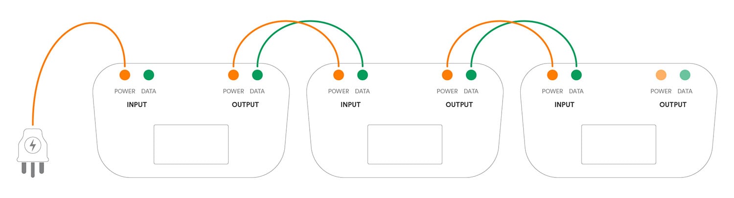
Daisy-chaining
Phase 06: Vacuum forming
At this point, we were pretty happy with the improvements we’d made on our design. But we were still desperate for an affordable way to build the enclosure. No matter what we tried, the device’s size and shape were giving us trouble.
Many hours of research and back and forths with industry people eventually led us to vacuum forming. Finally, we were looking at a method that could produce large forms relatively cheaply.
Vacuum forming works by warming up a sheet of plastic and then sucking it around a metal mold with a vacuum, before cooling it down to its rough shape. Multi-axis CNC curves the final shape and adds all the necessary features (slots, holes, etc). Metal molds are somewhat expensive but they don’t require an injection molding level of surface finish and they can be ‘pre-tested’ with resin replicas in the prototyping phase to optimize accuracy.
Emboldened by this discovery, we decided to reverse our engineering process: instead of trying to find the best production method for our design, we would now adapt our design to fit this new promising production method.

Initial vacuum forming study
Vacuum forming turned out to be a great option. But there was also a flip side. When creating the shape, only the side of the plastic that touches the mold produces accurate results, whilst the opposite side fluctuates, resulting in wall thickness variations across the part. To give an example, if you are making a box with a lid, using the exact same set of molds and conditions for every part, you will end up with some lids that fit the box perfectly, some that fit loosely and others that won’t fit at all. Further complicating matters, the accurate side is not aesthetically pleasing as the texture is compromised by contact with the metal surface. Conversely, the inaccurate side maintains almost all of its original texture and appearance.

Vacuum forming exploration
It was clear that obtaining an immaculate result would require some creative thinking to work around those limitations. Now, our setup consisted of a case (top shell), which would wrap around a lid (bottom shell). After some thinking, our solution was to use a male mold for the case and a female one for the lid. By doing so, we got a case that looked good on the outside and was accurate on the inside, which was important as it needed to accommodate the electronics and fit around the lid. Conversely, the lid would have an accurate outer surface, ensuring a fit with the case, and the ‘ugly’ sides wouldn’t be visible except at the bottom. Well, we couldn’t leave an ‘ugly’ side exposed anyway, so we sandblasted the female mold in order to improve the bottom part’s texture.
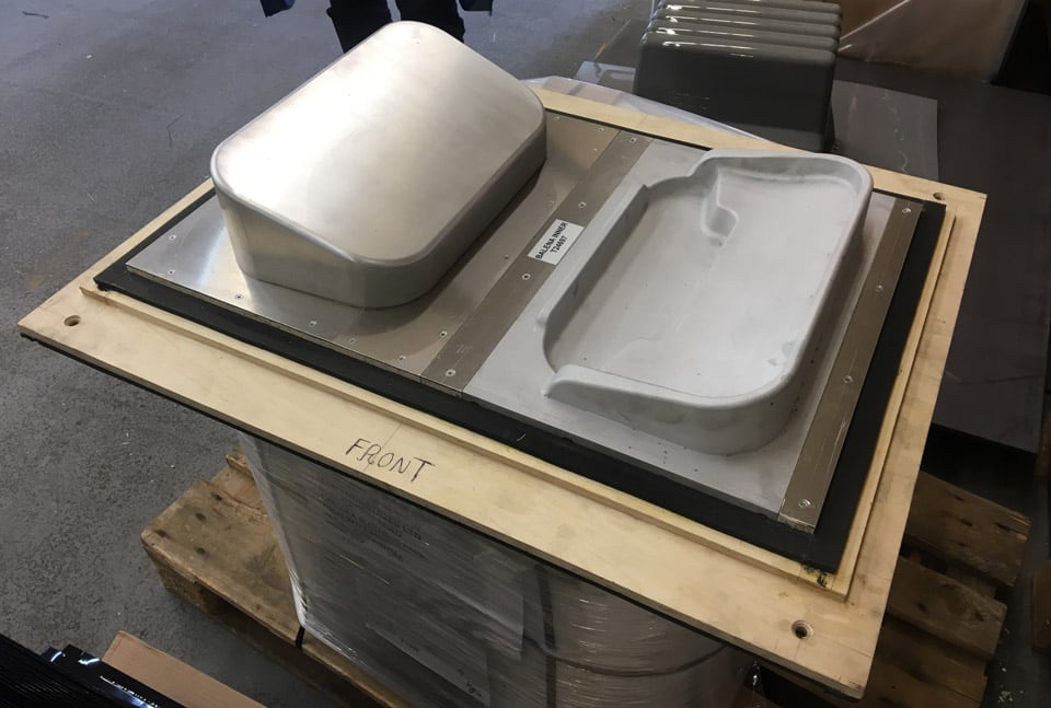
Vacuum forming tools (metal molds)
The finish line was in sight. But there was one last problem. The ‘pretty’ side was now on top but the wall thickness varied around the slots. For SD and USB this is not a huge issue but for microSD it could make it difficult or even impossible to unplug a card. In addition, creating the tiny slots with CNC leaves an unpleasant surface finish on the edges.
Once again, we needed a creative approach. We eventually solved it by introducing an injection molded part in the assembly, which had just the right size to cover one card reader, exposing its ports, and could be multiplied to cover all the device’s card readers. In the past, injection molding proved to be unsuitable for the enclosure, but such a small part would only require a cheap mold, while adding great detail and accuracy where is vital.
Injection molded insert
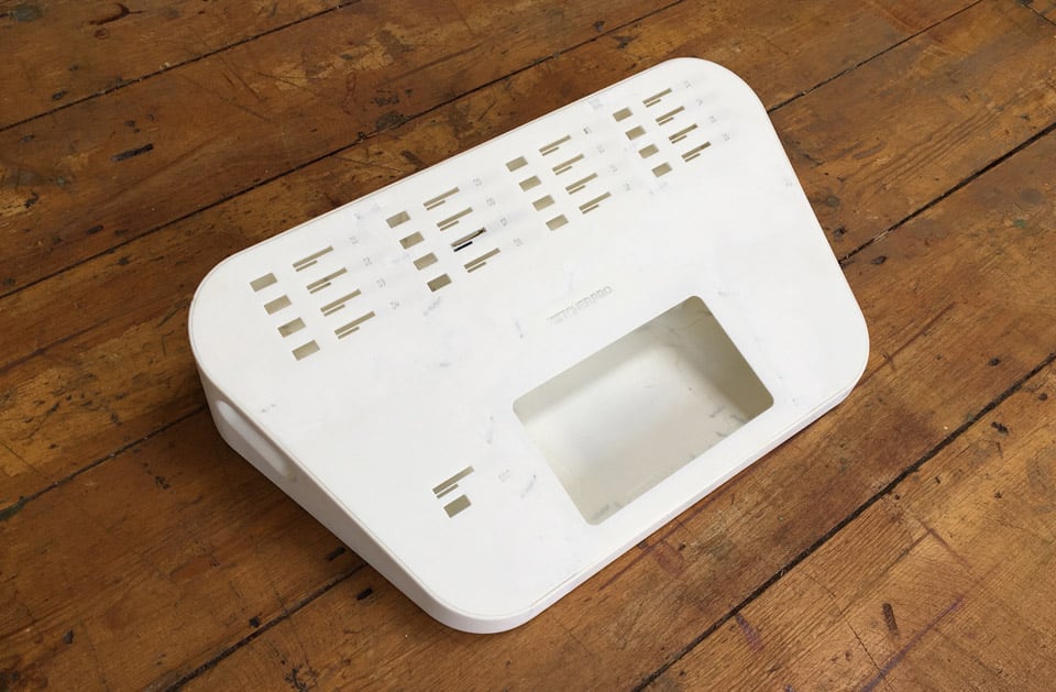
Vacuum formed shell with injection molded inserts
Phase 07: Can we make it simpler?
By now, we were satisfied with our design both from a hardware and enclosure perspective. But we felt there was room for optimization. Remember, our goal was to make this as simple, easy to use, and cheap as possible.
One area we looked at was costs. The bill of materials was getting closer to what we had planned, but when looking at where we could cut costs further, we found ways to remove some hardware. This also had an additional benefit of improving the user experience.
One example of this was the power switch. We found that we could replace it with a ‘touch to wake’ functionality in the UI. As a result, when you have a stack of devices, the leading EtcherPro can put to sleep or wake up the whole stack — in the previous case, users would have had to manually press all the physical switches of the stack. In turn, the dedicated source slot located next to the screen was removed and replaced by an input/output slot. A dedicated fuse box was replaced by a power supply with an embedded reset fuse. All these changes simplified our product and made it more intuitive for the user.
We also found that we could optimize the fastening system. Originally, the two shells were held together with screws. These would fasten onto welded plastic inserts on the inner part, and special pillars would be welded to secure the PCB in place, heavily increasing the assembly cost. But we were producing the injection molded inserts anyway (for the card readers), so we thought that they could serve multiple purposes. We therefore added two small pillars to the inserts, which could accept standoffs using metal threaded nuts. The standoffs could support both the PCB and the bottom shell. The array is: screw > bottom shell > standoff > PCB > standoff > injection molded insert (see diagram below). The front part of the bottom shell that accommodates the power supply had also to be supported somehow. Therefore, two plastic pegs were welded on the top shell on which the bottom shell would slide into before securing the screws.
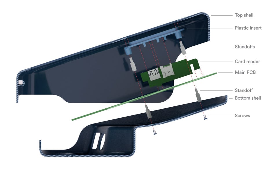
Assembly – cross section
Assembly – cross section
A hard look at our daisy-chaining also revealed new possibilities. Until then, the stacked devices were held in place using magnets glued on the inner surface of the back and front of each device. This approach carried the risk that the magnets could come loose. It also required special attention during assembly to ensure the magnets were installed with the correct polarity so devices would attract each other. But again, we were producing the front pegs anyway, so this part could also act as housing for the magnets. The magnets themselves were replaced by custom manufactured ones that are smaller but more powerful. The back magnets were replaced by a magnetic stainless steel sticker at the back of the device that has printed info about the power and data sockets.

Front pegs and magnets – cross section
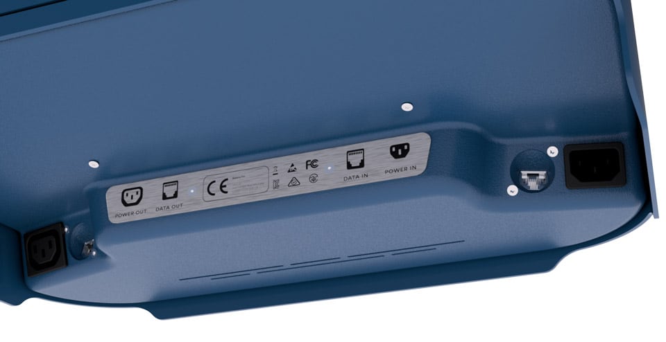
Magnetic stainless steel sticker
To tidy up the power and data cables we were using to connect the devices, we had to design an effective cable management system. We first moved all the power and data interfaces to the back of the device, placing the inputs on the one side and outputs on the other. The top shell was extended further to the ground, creating legs and allowing additional space underneath the bottom shell. The cables could now be nicely routed from the output of one device to the input of the next one.
Cable management
Next, we rethought the ethernet ports. These were originally designed as two separate small PCBs that would mount directly on the bottom shell (panel mount). This turned out to be a complex and expensive solution due to the high speed and flexible board to board connector required. So instead, we extended the main PCB downwards, creating two symmetrical ‘legs’ that could host the ethernet ports, exposing them directly to the case openings. A small 3D printed adapter was added to bridge the gap between the ports and the shell.

Ethernet adapter (yellow)
Finally, we designed a simple holder for single board computers that can be plugged directly into the EtcherPro. The holder is made out of two layers of acrylic held together with standoffs. It’s really cheap to make, even at small scale, and anyone who wants could potentially reproduce it using a laser cutter or 3d printer. We feel this holder is a good starting point; we have plans to produce a more advanced version that could potentially offer hardware testing capabilities.
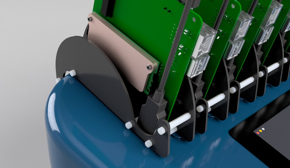
Single-board computer adapter
Thoughts
EtcherPro has been a hardware academy for us. Our commitment to removing as much friction as possible in the manufacturing and assembly of EtcherPro led us to revamp traditional production processes. We carefully optimized components and processes at a design level, lowering the margin of error. This not only allowed us to reduce the bill of materials but also it significantly streamlined the assembly. From the form factor down to the assembly process, we wanted all aspects of our product to be beautiful.
In the end result, most components are unified and serve a double or even triple role. The injection molded inserts for instance host the card readers and support the PCB and the bottom shell. In addition, we are pre-assembling components at their most relevant stage. Most electronics are mounted on the main PCB by the hardware manufacturer, while plastic inserts are welded by the vacuum forming manufacturer. Workers in our assembly line will have to deal only with sub-assemblies, making the process fast and efficient.
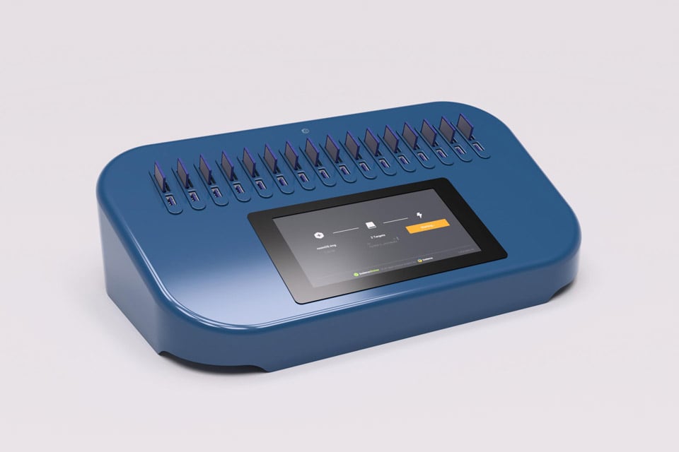
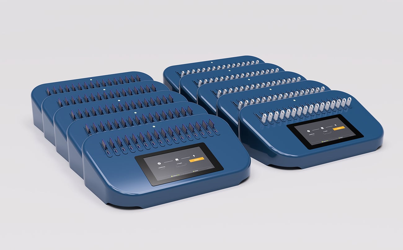
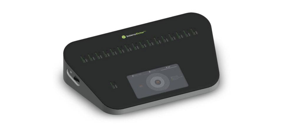
Final EtcherPro design
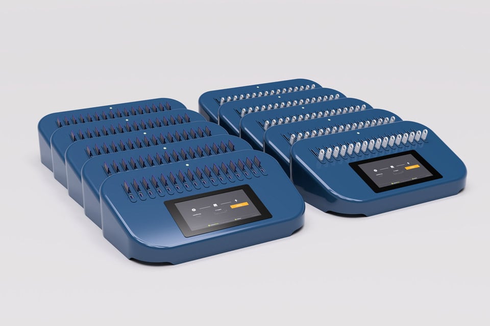
Daisy-chained EtcherPros

Daisy-chained EtcherPros
Phase 08: Are we ready for production?
By now (mid 2019), we’ve wrapped up the product development work and are actively tying up all the loose ends before moving to production.
We’ve run some basic speed tests with single drive flashing, exceeding 150MB/s. As soon as we receive some PCB prototypes, we’ll be able to test multi-writes and daisy-chaining. Our goal is to offer +60MB/s when flashing multiple drives.

EtcherPro DevKit
We’ve carried out thermal stress tests on the enclosure and validated that even in extreme scenarios (PSU temperature exceeds 120℃), the structure is not compromised. Next, we’ll test how a complete device performs when flashing multiple drives at high speed and validate that peak performance is sustained.
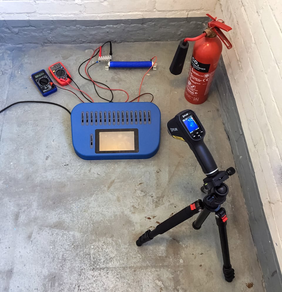
Thermal testing
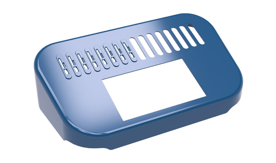
A couple of months ago we carried out a twitter poll for the colour of the enclosure. Following that, we explored a couple of different options and we ended up with ‘Pantone 2188C’. To ensure that injection molded and vacuum formed parts will look identical, we produced all plastics from the same custom coloured pellets. We have received samples of the final shells and part fitting looks great.
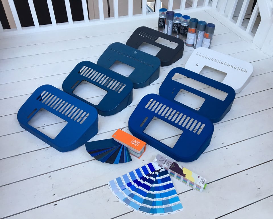
Case color exploration
The last big step before moving to production is testing the device in an independent lab to ensure we comply with US, EU and UK regulations and obtain all relevant certifications. We have already placed bulk orders for components with long lead times and we’ll kickstart assembly once we validate the product. In the meantime, we are planning to send prototypes to beta testers to obtain early feedback.
Pre-orders and price
Preorders will open around October aiming to start shipping devices before the end of the year. We are targeting a price of around 990 USD per device.
Want to stay updated about our progress? Subscribe to our mailing list.
PS. EtcherPro is a hackable platform
Working on this project, we realised that EtcherPro is a programmable hardware platform. Its basic primitives are the building blocks that can be used to satisfy a wide range of use cases. It is remotely updatable/ controllable, it has a large touch screen for physical interactions, it has 16 x interchangeable high-bandwidth and powered (USB 3.0) slots, and it can be daisy-chained to extend capacity. While we don’t intend to start building out new product lines, we really enjoy doing some thought experiments on what else can you possibly make with this platform. Here are some ideas we had:
- Network-attached storage extendable system
- Synchronised audio-visual recorder
- BT headset coordinator (e.g. conference calls)
- Modem bonding platform
- Hardware prototyping platform
And here is a challenge for you. Can you think of another use case for the EtcherPro hardware platform assuming you could write new software? Write your ideas in the comments below.
Thanks for the excellent write up of the process you took. I had wondered what happened to this project – as a non-hardware guy it sounded reasonably straight forward at the beginning, but you helped me appreciate the twists and turns both in function and purpose along the way.
I had a couple of ideas for re-purposing the base hardware: cluster controller for multiple SBCs with network over USB and utilising MicroK8s, or as a central power and feed manager for a group of CCTVs. It may only need a change in case design for some of these to work?
Hello @Andronichus for your message. Welcome to the balena forums!
To get the latest update of the project you can find here more information EtcherPro progress updates – #67 by konmouz tldr we are starting to deliver first units to customers.
Not sure if this may work, but let me ping @konmouz to learn about this
Hi @Andronichus, thank you for your interest in EtcherPro. I’m not super familiar with the usecases you describe but they sound feasible. Also, maybe you could get away from altering the case, but instead design a jig/adapter that could sit on top. Software-wise, EtcherPro owners are welcome to take over the code of their device and build anything they want.