
Editor’s Note: The Ribbit Network project is a balenaHub Challenge winner. This guide is contributed by the project creator, Keenan Johnson. Try it out and join this amazing citizen science effort. Congratulations, Keenan!
The Ribbit Network is a large network of open-source, low-cost, Greenhouse Gas Detection Sensors. This citizen science project aims to create the world’s largest Greenhouse Gas Emissions dataset that will empower anyone to join in the work on understanding climate, and provide informed data for climate action. Learn how to build one and join the global effort.
Our ‘Frogs’ are tiny sensors that you can build or buy and deploy at your own home! It’s a small, open-source box that measures the amount of CO2 in the air using a tiny laser. It’s easy to set up and will constantly record valuable scientific data on our climate. Frogs are one of the species that are most affected by climate change! Just like our sensors, they ribbit to one another to create a powerful network of data about the environment.
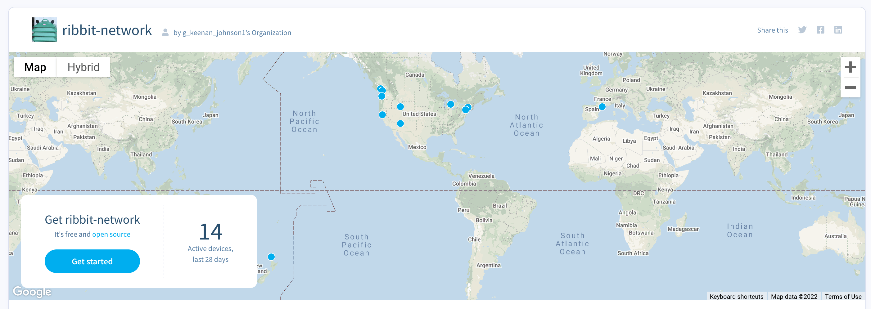
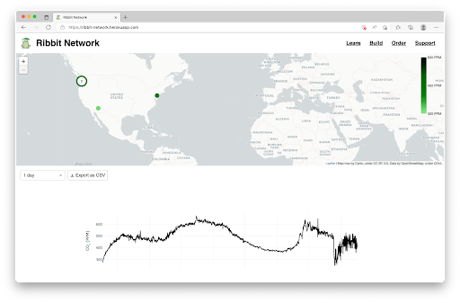
The first prototype sensors are already up and running, and now it’s time to begin scaling and collecting more data! Here is the live data from our sensor network.
Tutorial
Hardware required
Data collection
Compute / Connectivity
Cables
- Power Supply
- STEMMA QT / Qwiic JST SH 4-pin Cable 50mm Long
- STEMMA QT / Qwiic JST SH 4-pin Cable 100mm Long
Additional materials
If you want to build the “Frog” enclosure (recommended for outdoor installation, and, well, to look like a frog)
Mechanical parts
3D-printed parts
Consumables
Software required
- Check out the Ribbit Network open fleet on balenaHub
- balenaEtcher, to burn the OS image onto your SD card
How it Works
As you can see from the Hardware list above, a Beaglebone Green is used as the central compute platform, and it has a series of sensors attached to measure CO2, temperature, humidity, barometric pressure, determine location via GPS, and connect to WiFi to reach the internet. All of the software for the project is pre-written, and simply gets deployed onto the Frog. The software is also open-source, available on GitHub here: https://github.com/Ribbit-Network/ribbit-network-frog-sensor
For those who are curious, three main Docker containers are run on the Frog:
- CO2 – This container runs the main python script responsible for connecting to the CO2 sensor and publishing the data to the InfluxDB database.
- GPS – This container configures
gpsdto connect to a gps device for receiving the device location. - WiFi Connect – This is a git submodule to the wifi connect repo. This allows easy reconfiguration of the sensor’s wifi connection.
Again, no need to worry about writing or editing any of these containers though, they will automatically get built and deployed to your Frog further down this tutorial. 🙂
Build steps
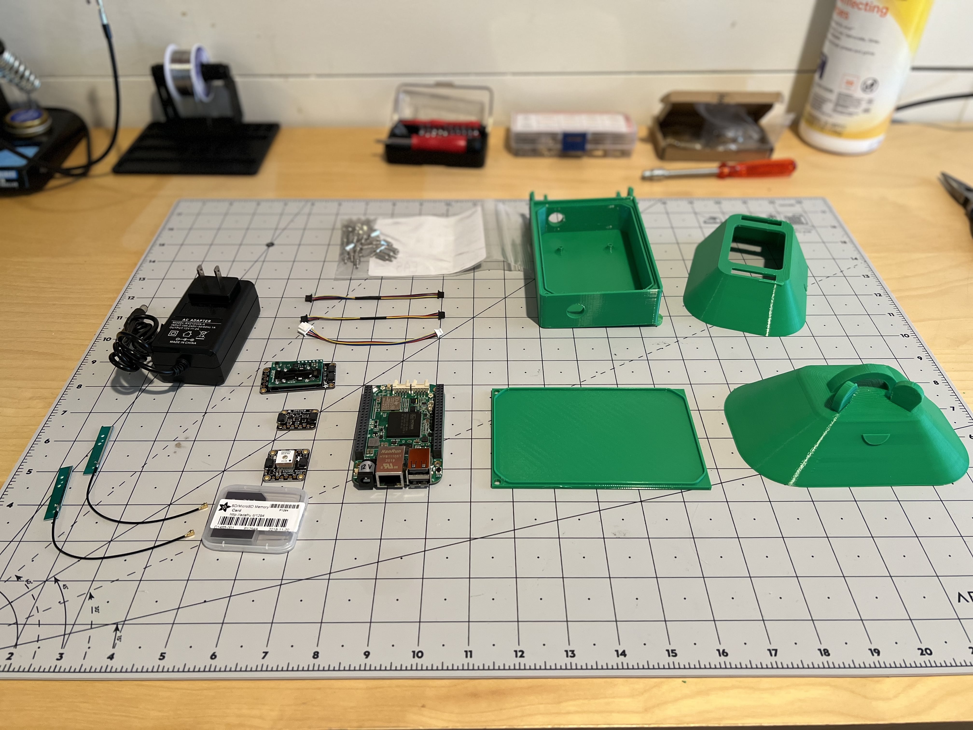
The first step in building a Frog Sensor is to get all of the parts. You can find a more detailed parts list here which includes links to purchase and quantities.
NB There are several 3D printed parts that you’ll need to 3D print yourself.
3D Printing
Given that the sensors are designed to sit outside, a PETG 3D Printer Filament should be used for all the parts. This kind of filament is readily available and can be used on almost any 3D printer. It holds up well in moisture and is very UV resistant making it perfect for the sensor. The parts list links to some suggestions for brands and colors.
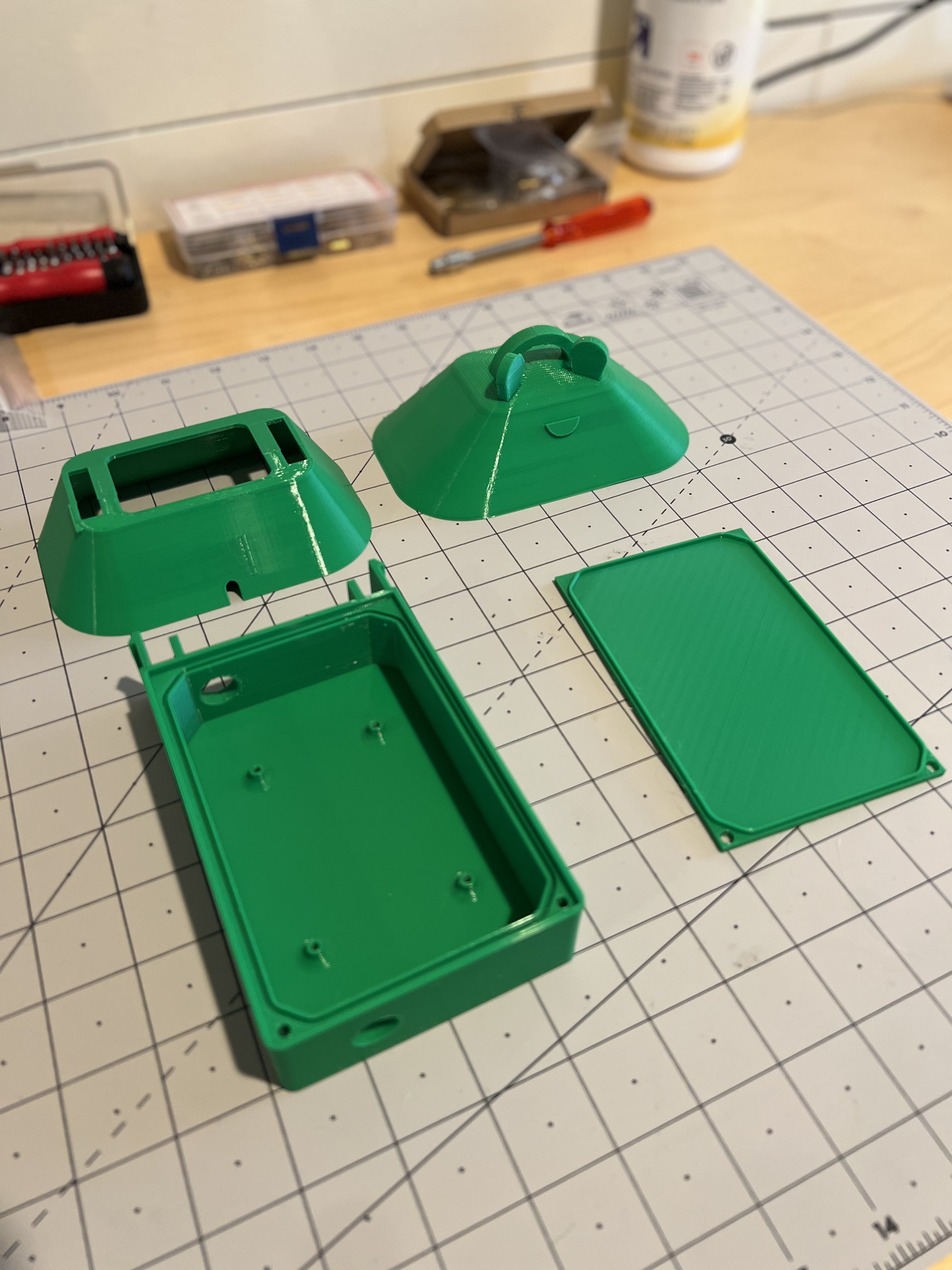
These are the parts required for the Frog Sensor construction, you need one of each and we suggest using green filament for maximum frogginess:
* Enclosure Base
* Enclosure Lid
* Lower Shroud
* Frog Head – with eyes
These parts only serve a cosmetic function and are optional. However, they are fun and cute and make your sensor look more froggy:
* Frog Head – no eyes
* Quantity: 1
* Suggested Color: Green
* Frog Eyes
* Quantity: 2
* Suggested Color: Block
* Frog Mouth
* Quantity: 1
* Suggested Color: Pink
Software
Now it’s time to install the software we need on the SD card for the Frog Sensor. You’ll need a SD card reader and SD card for this step
Download the software
First download the latest software from the Ribbit Network balenaHub Fleet.
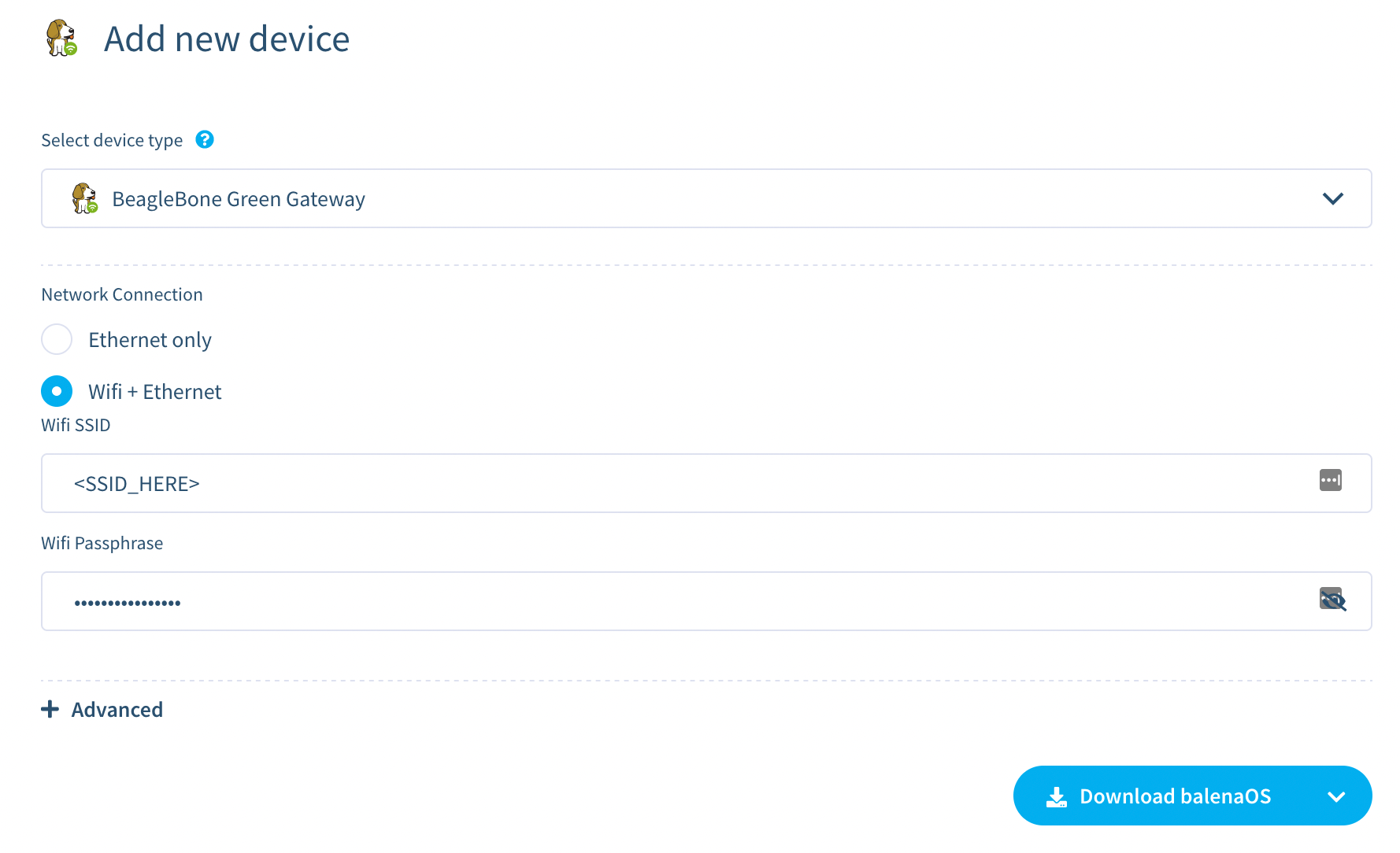
The next screen will present you with a few options. For device, select BeagleBone Green Gateway (You can also build the Ribbit V1 which requires a Raspberry Pi). For network connection, you’ll want to select “Wifi + Ethernet” and enter your wifi connection details.
Then click “Download balenaOS” and follow the instructions that pop up to get your image.
Flash the SD Card
We recommend using Etcher to flash the downloaded file onto your SD card.
Once the SD card is ready to go, insert it into the Beaglebone Green Gateway per the instructions from balena.
Power up the device while holding down the small button near the SD slot. You need to keep it pressed until the blue LEDs start flashing wildly.
Wait 5 seconds after the blue LEDs have stopped flashing wildly, then remove power from the board. On some boards the LEDs will shut down completely. Remove the balenaOS installation SD Card.
Now your device has its software flashed directly to the board and is ready to go!
Assembling Your Device
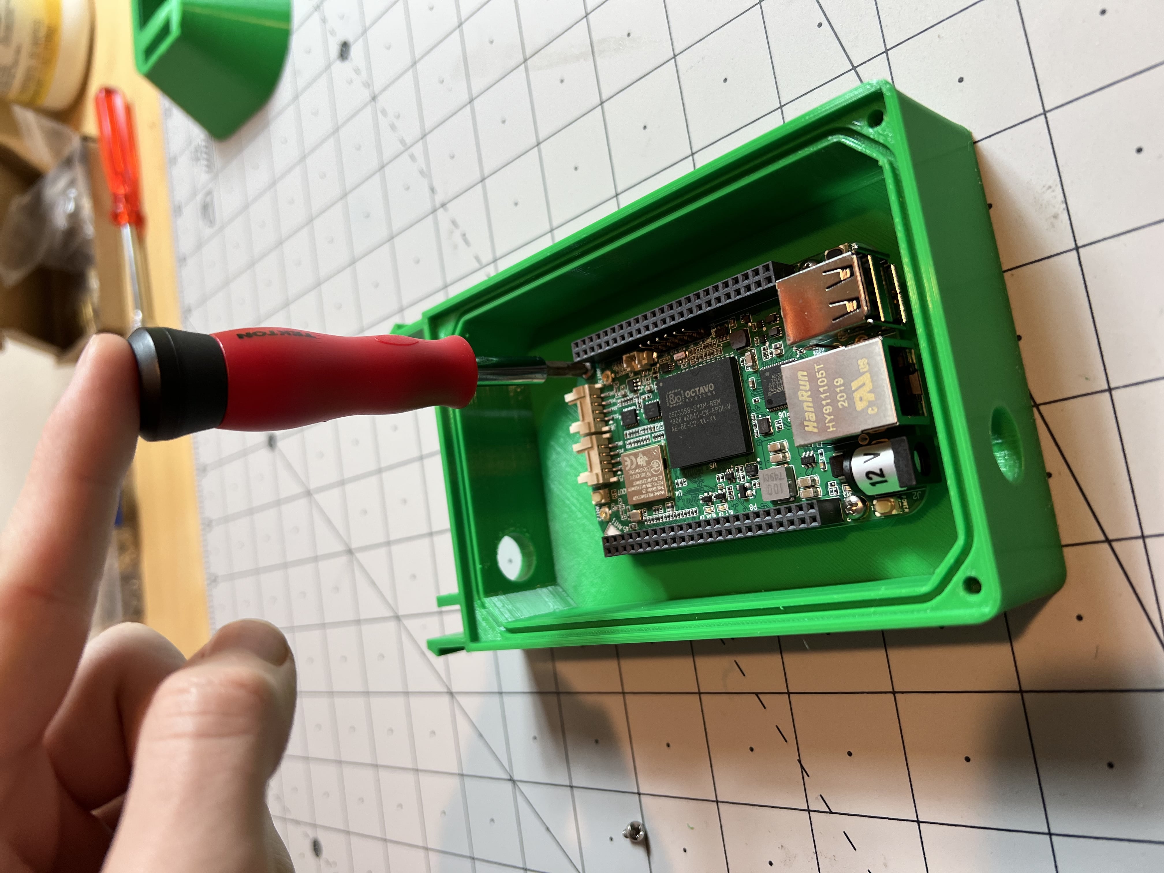
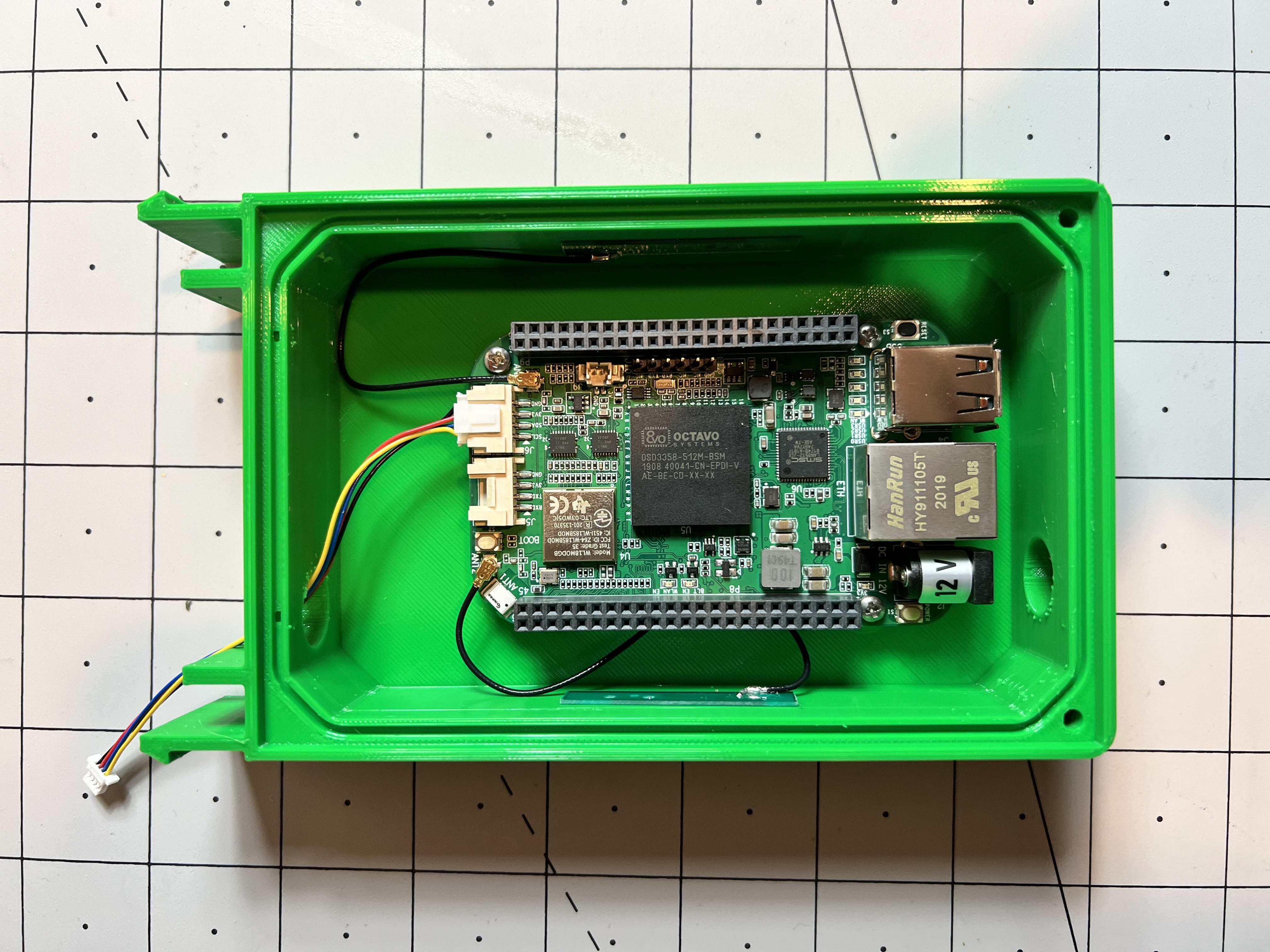
The first step is to mount the Beagle Bone in the main enclosure box. Place it on the mounts as shown below.
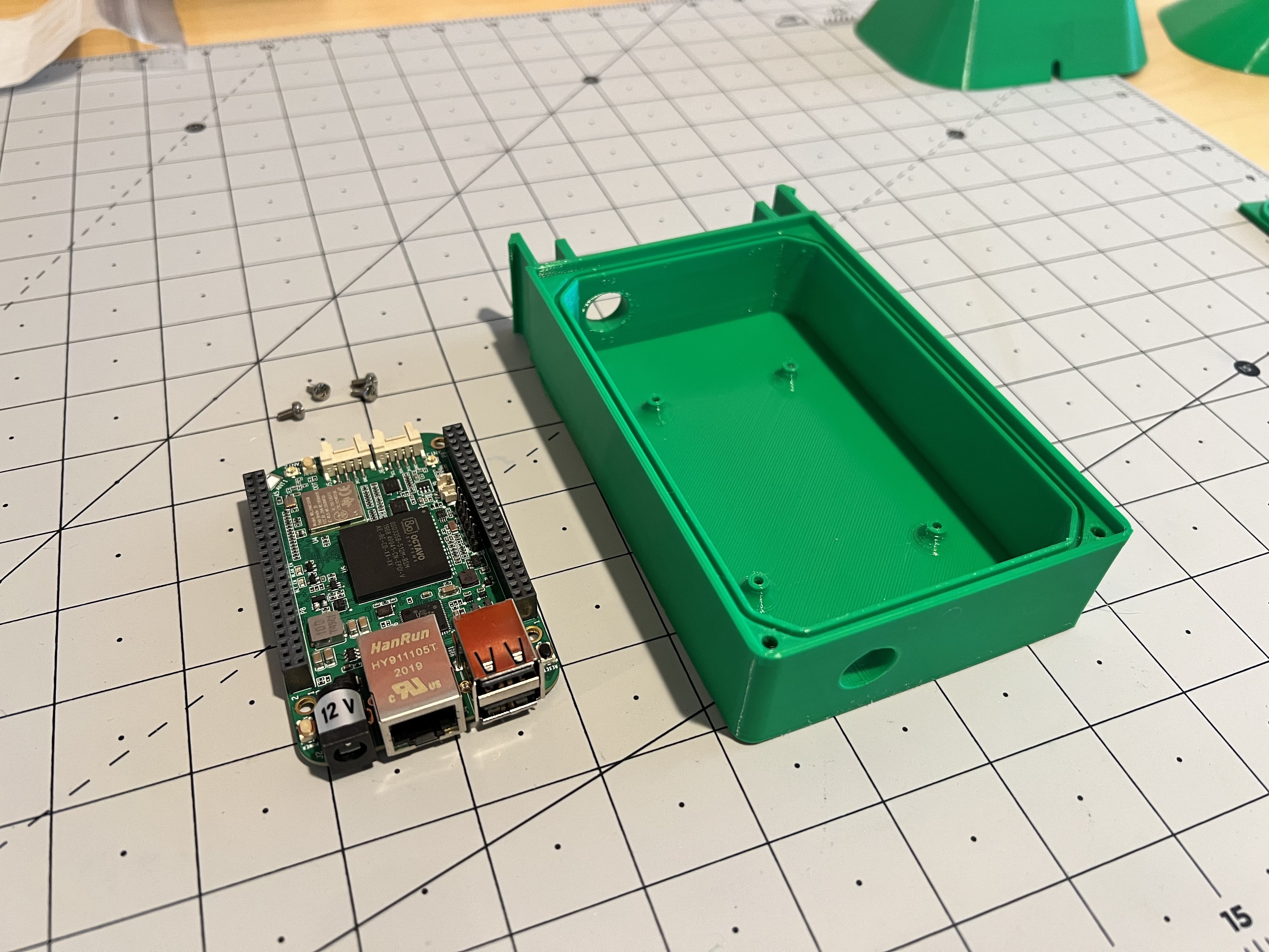
Then attach using 2 M2.5 screws. Careful not to over tighten into the 3D printed box.
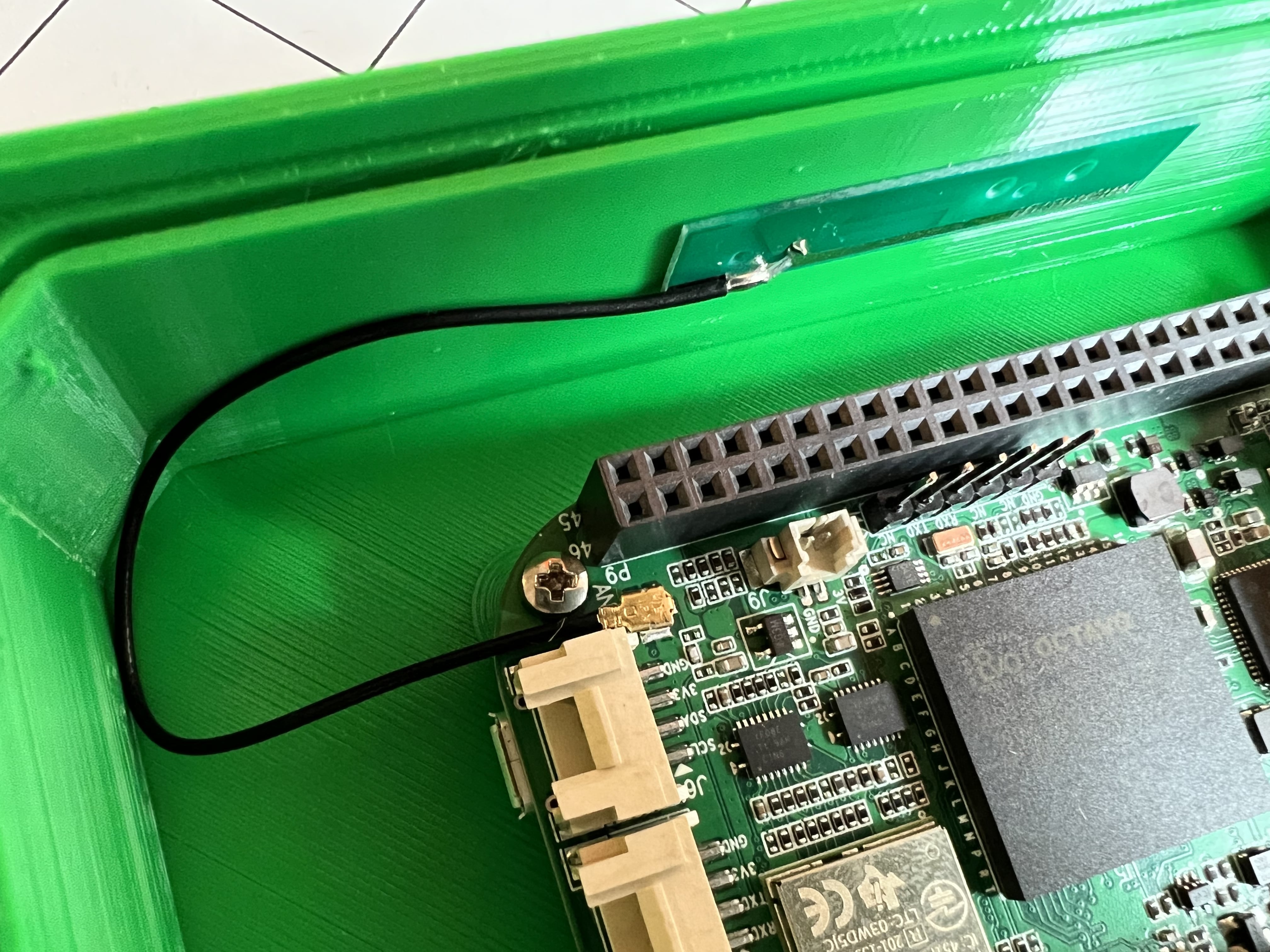
The Wifi Antenna needs to be connected to the Beaglebone and adhered to the inside of the enclosure box. Remove the adhesive backing and stick to the inside of the enclosure. Next, connect the antenna connector to the board as shown below. Repeat for both antenna.
Connect the Groove to QWIIC cable from the right I2C port on the Beaglebone as shown below and route out of the hole in the top of the enclosure.
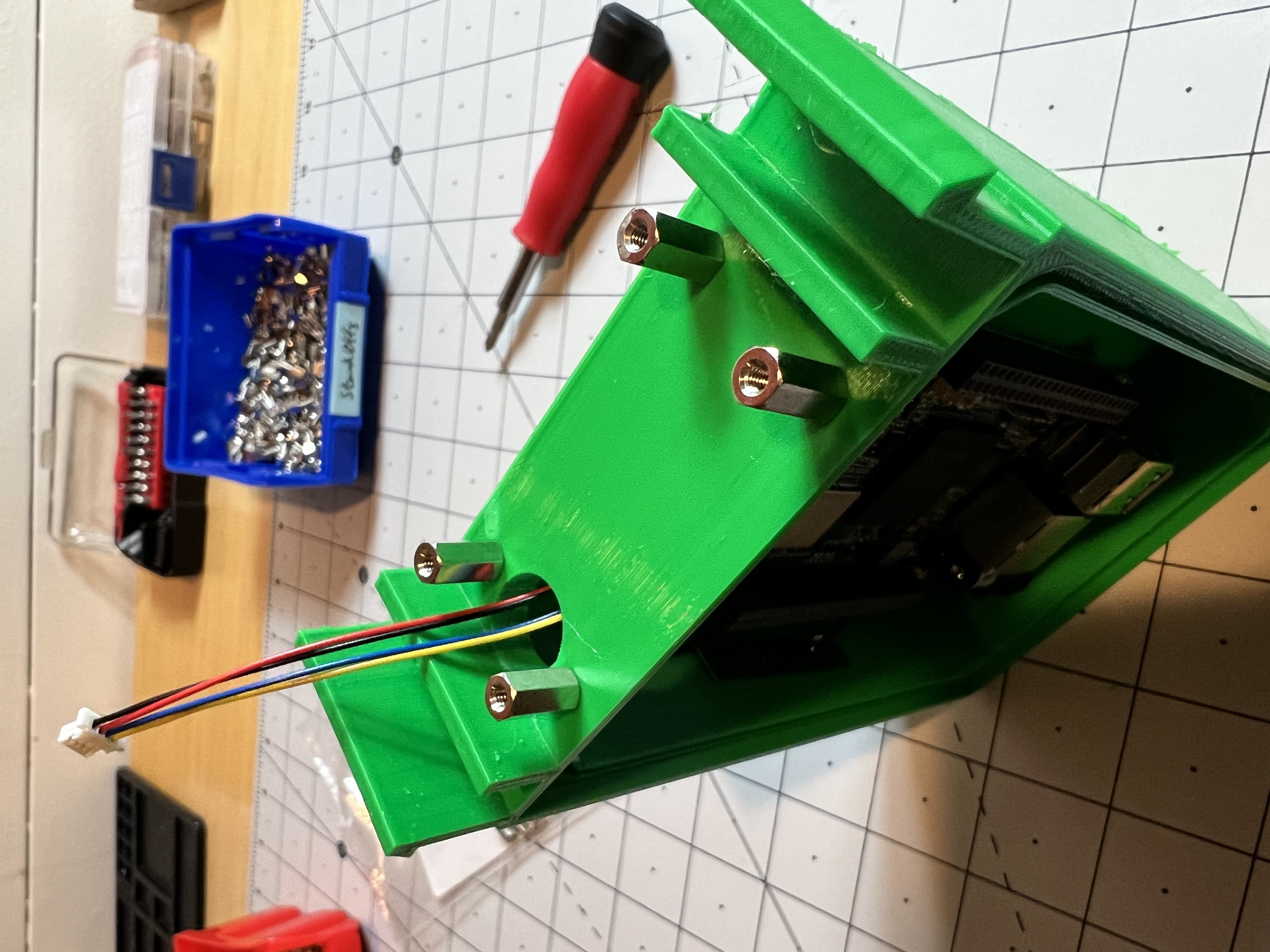
Next, the mounts for the CO2 sensor need to be installed. Screw four of the standoffs into the holes in the top of the enclosure box as shown below:
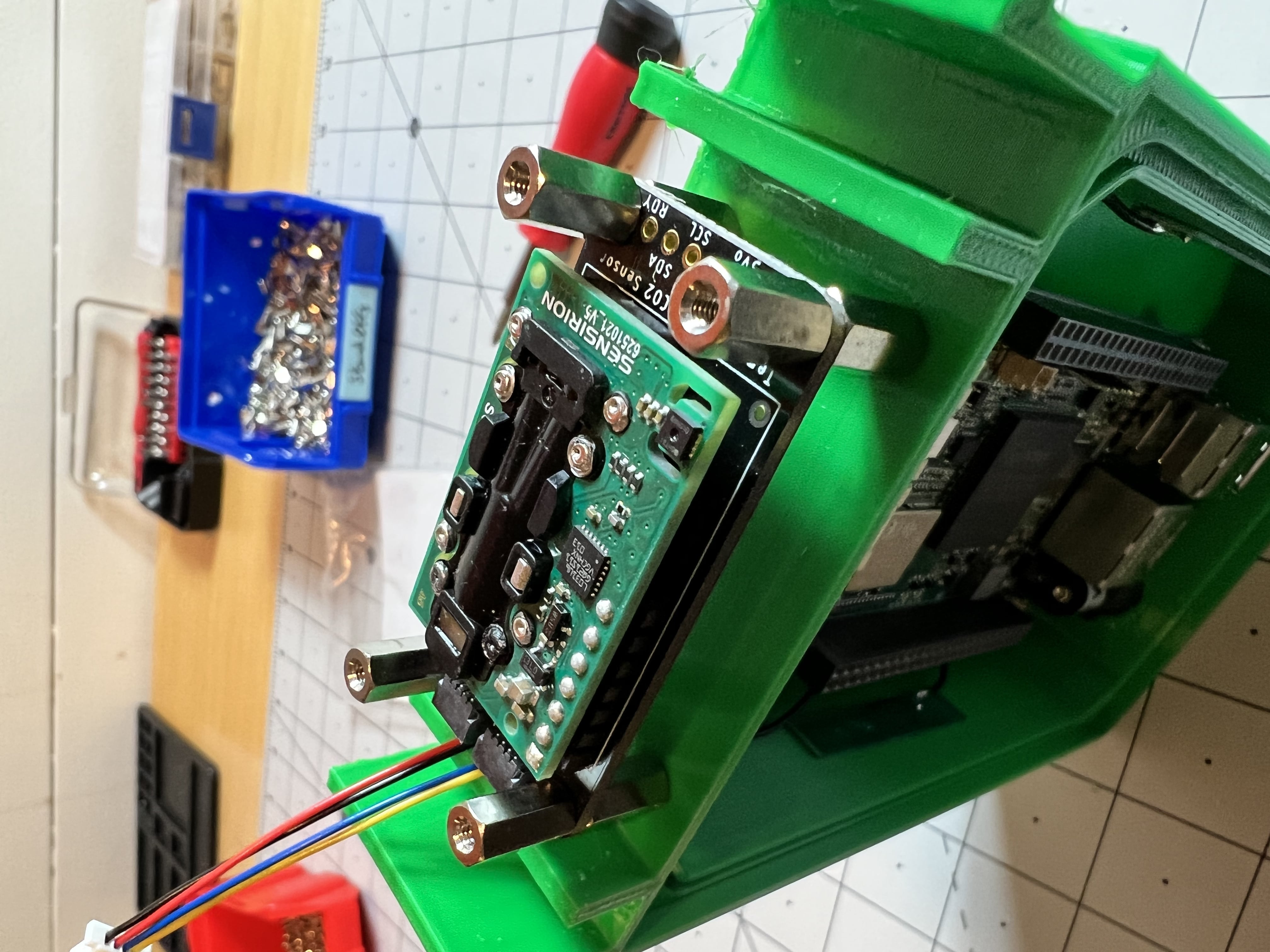
Mount the CO2 Sensor onto the standoffs as shown below.
Mount the GPS onto the standoffs using two screws as shown below.
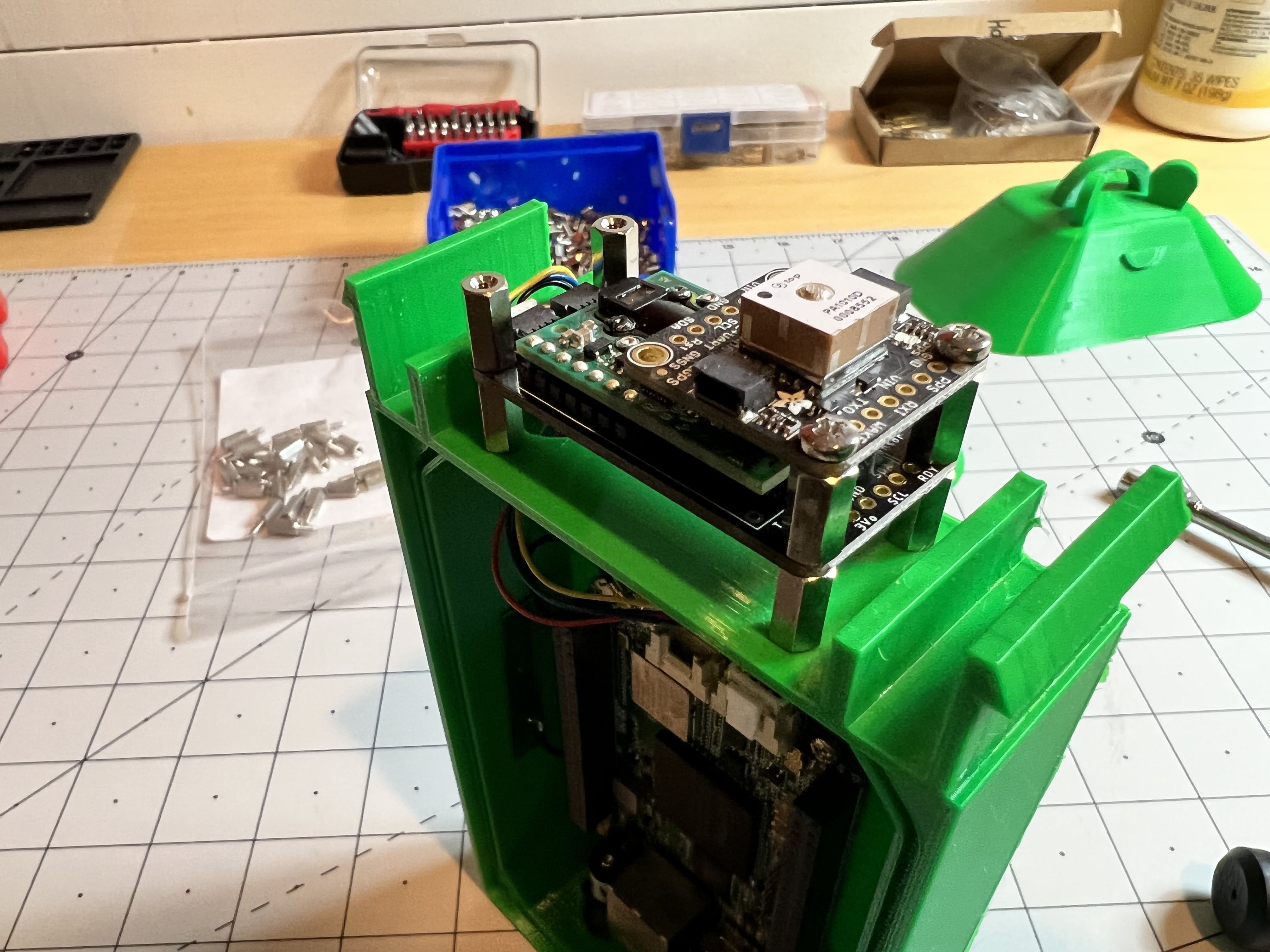
Mount the Barometer onto the standoffs using two screws as shown below.
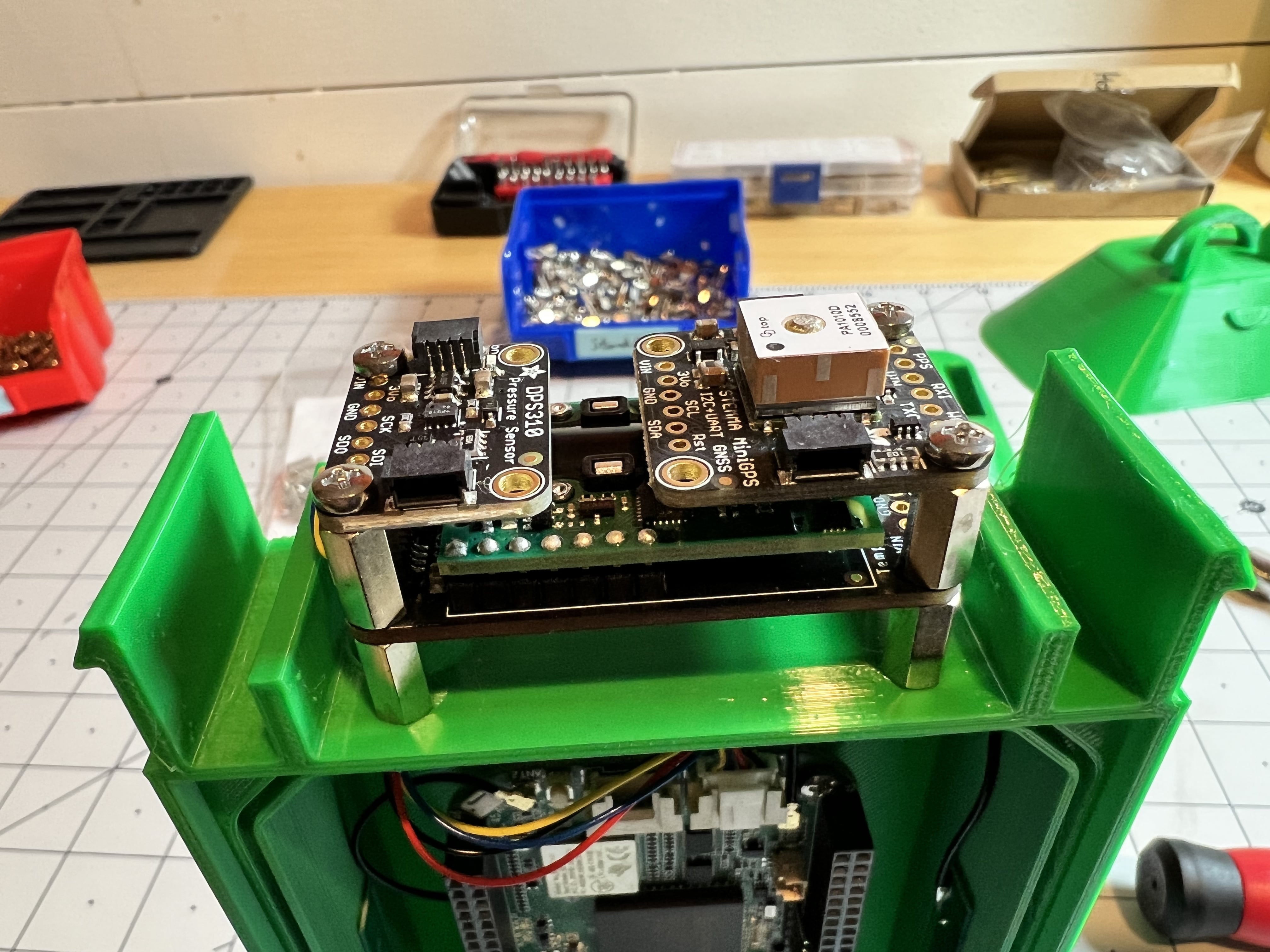
To install the sensor cables, use one of the short cables to connect the GPS to the Barometer as shown below:
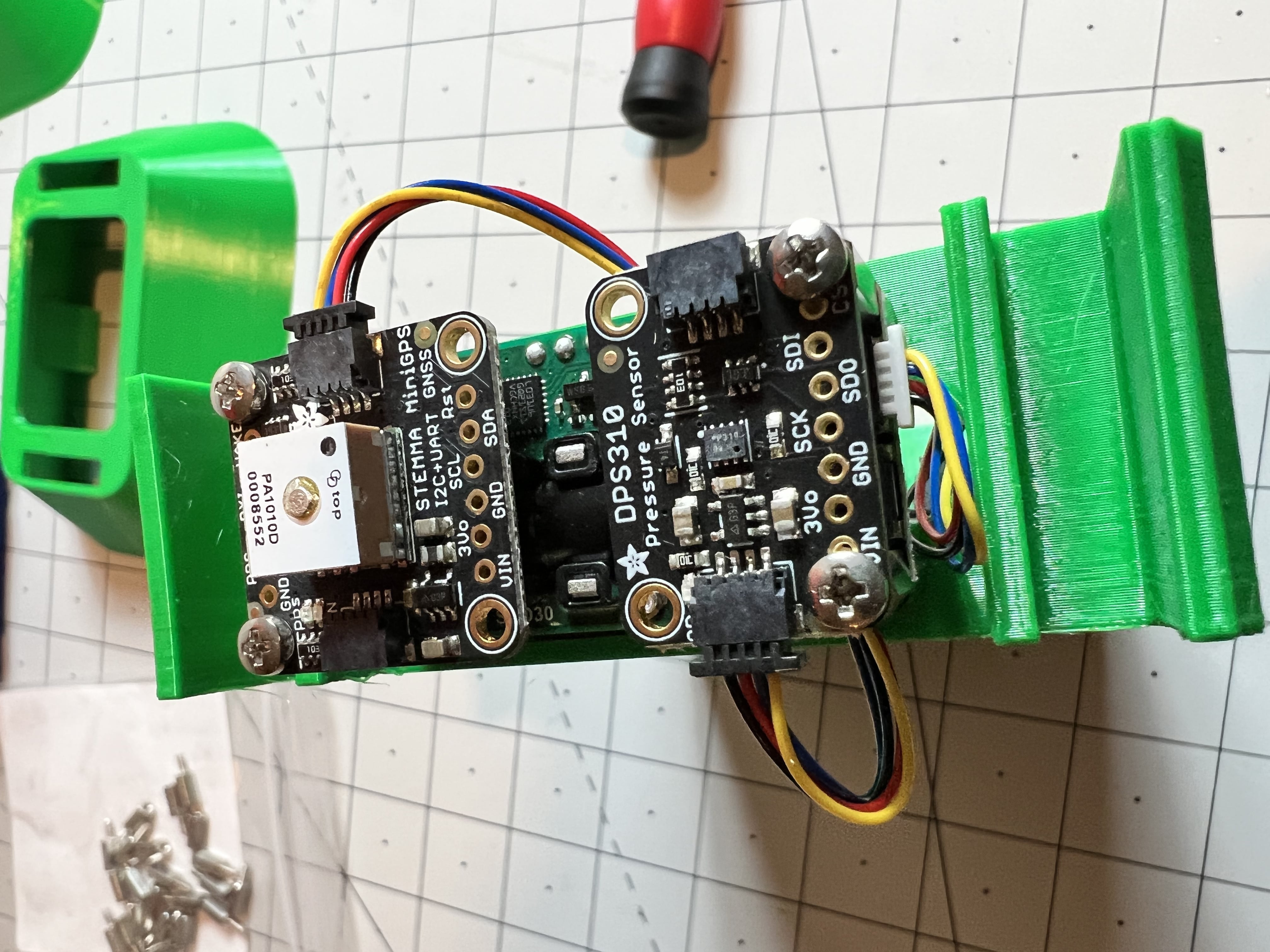
Now, use the second cable and connect the barometer to the CO2 sensor. Make sure the second port of the CO2 sensor is connected to the cable coming from the Beaglebone in the box.
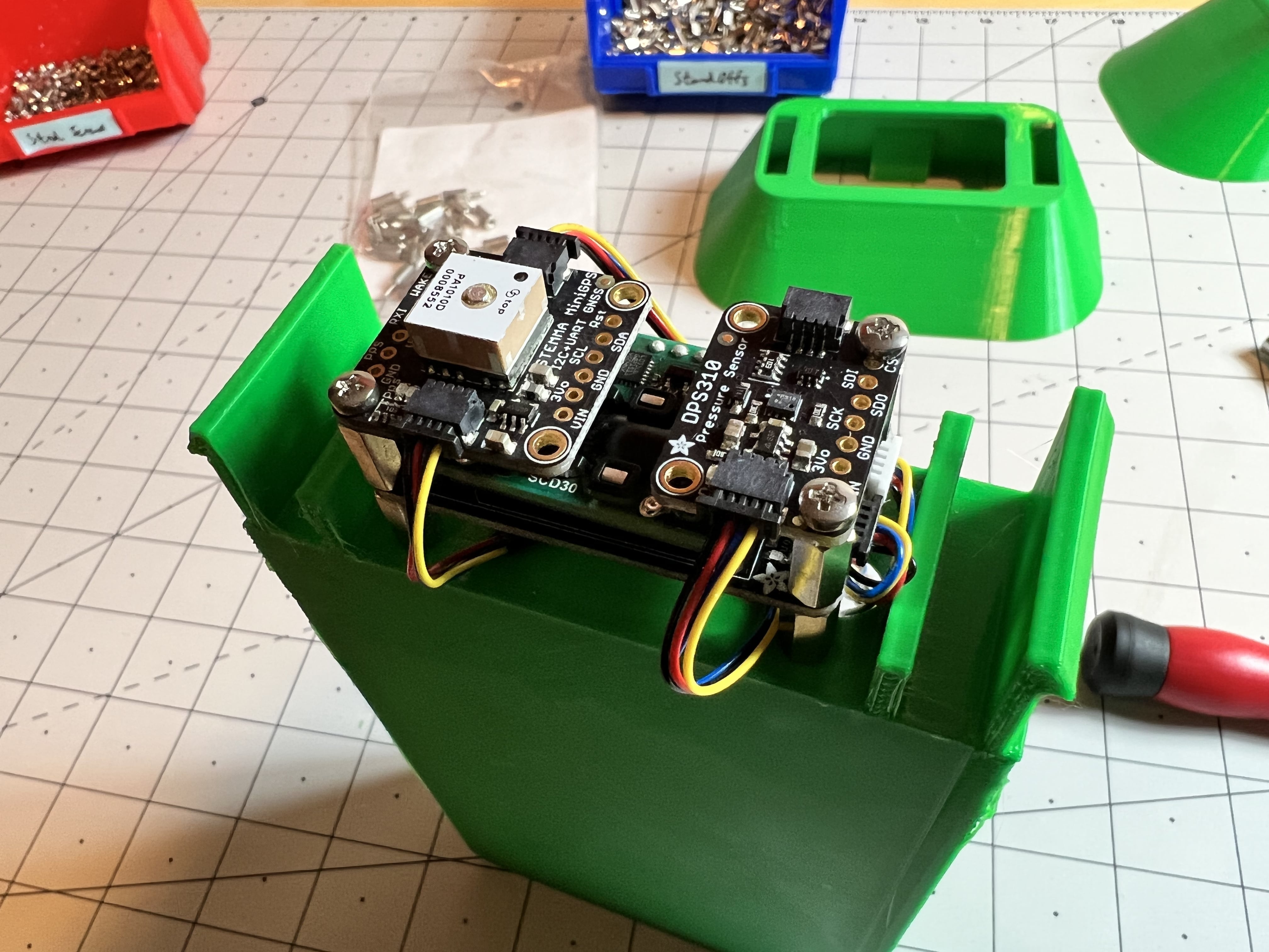
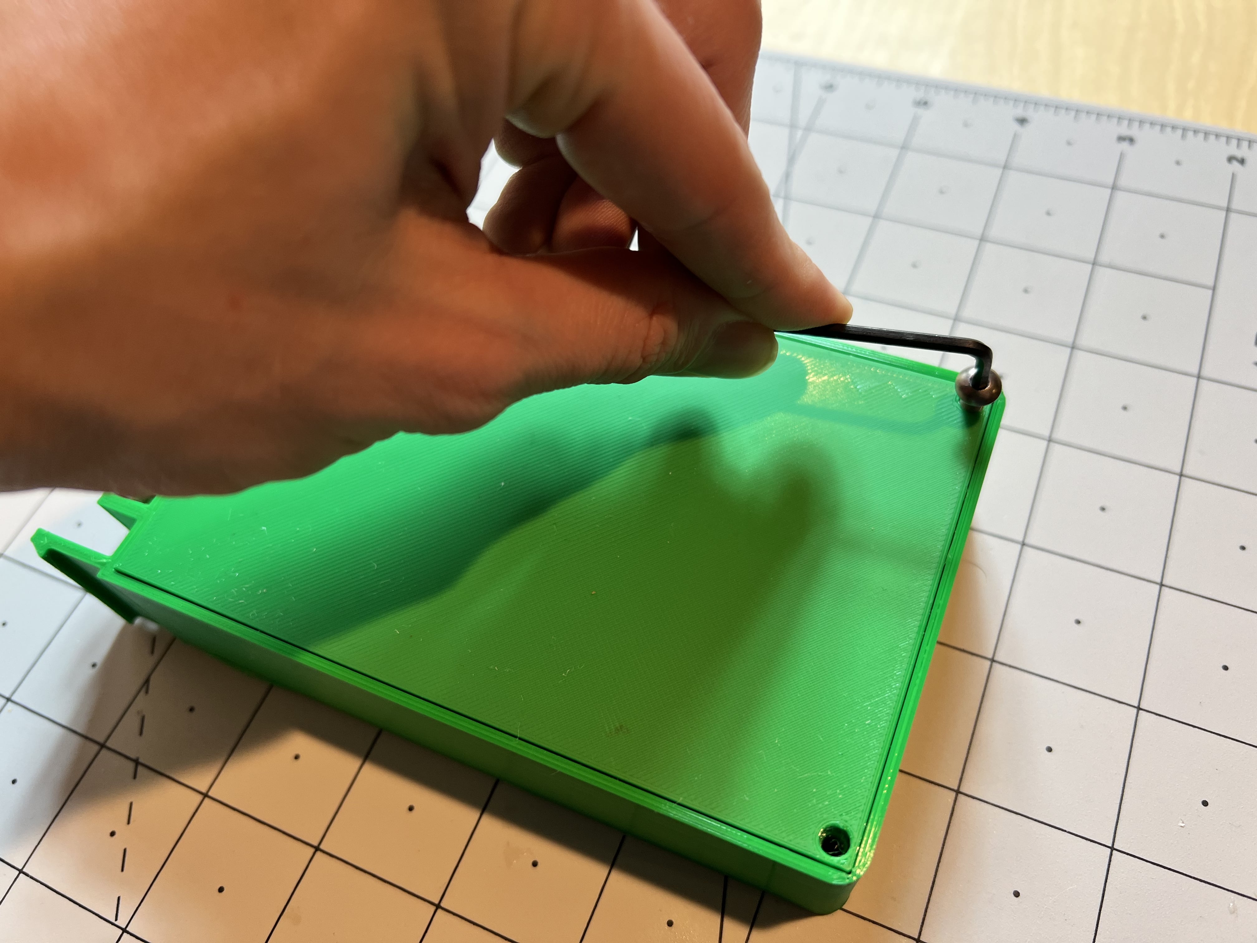
Now that the electronics are all done, the protective shroud for the sensors can be installed. Make sure the mounting notch is towards the back of the box. Watch the wires and snap the shroud into place. Snap the head on and the final step is to place the lid on the enclosure.

Snap the lid into the groove and then use a hex wrench to install the two bolts at the bottom. Be sure not to overtighten into the plastic.
The assembly is now complete and you can place your sensor outside!
Place Your Sensor in its New Home
Now it’s time to place the sensor in its home outside your home.
You can use the loop on the top of the sensor to hang the sensor somewhere or use the slot on the backside to hang the sensor on a nail.
The location will need to be near a power outlet to ensure there is power for the sensor. Ideally it should be as high as possible and out of direct sunlight as much as possible to prevent rapid temperature changes. Try to ensure the space above the sensor is largely unobstructed so that the GPS unit can obtain an accurate position (don’t place the sensor in a shed for instance).
Power cable
Connect the USB power supply to the USB connector on the Beaglebone board and plug the sensor into a normal wall outlet.
WiFi connection
If you didn’t enter your home network WiFi information previously, or you purchased the Frog pre-assembled, you’ll need to connect it to your home WiFi network:
After the Frog sensor is connected to power, it will create a Hotspot called “WiFi Connect”. Connect to that hotspot network from a computer or smartphone to continue the setup.
Upon connecting to the hotspot, or by opening a web browser, you should be redirected to the page pictured below. Otherwise, open a web browser and navigate to https://192.168.42.1
On this page, select your home WiFi network (SSID) and enter the Password. This will connect the frog sensor to your home WiFi network.

Once connected, the sensor will now disconnect from your device, stop broadcasting the “WiFi Connect” hotspot, and connect to your home WiFi network.
You should see your sensor appear on this web page shortly. It could take about 5 to 10 minutes, as some software still has to download from balenaCloud. If your Frog does not appear within 10 minutes or so, it might be worth rebooting the Frog just in case.
Accessing the dashboard
Once your Frog is online and working, you will see your device’s data begin streaming into the Ribbit Network dashboard like this:
What’s next?
With your Frog deployed and transmitting data, you are contributing and helping scientists better understand greenhouse gases and climate change. The best thing you can do now, is share the project with others, and help them to build Frogs as well!
Thank you for checking out this article and joining the Ribbit Network, if you have any questions head over the the balena forums to start a new discussion here and follow the Ribbit Networks journey by joining their developer Discord channel.