

If you’re someone like me who can solder wires together, and knows how to program a single board computer to blink addressable LEDs, but always struggles when it comes to creating a beautiful front-end user interface to control them over the web, this blog post is for you.
Let’s explore how to interface edge devices on balena using AdafruitIO in a low-friction way. We’ll also build a really neat controllable LED project while we’re at it.
The idea
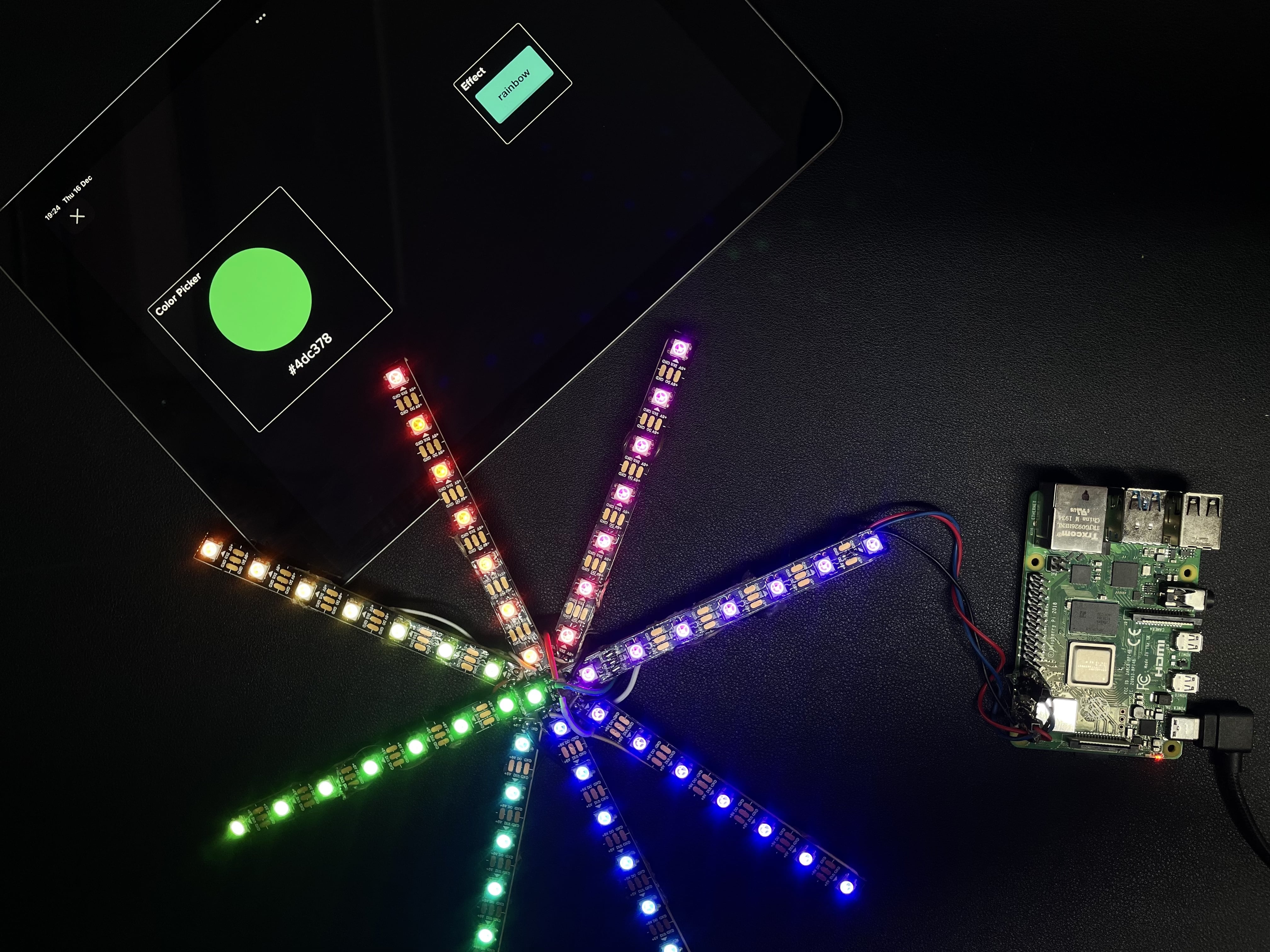
The holidays are that time of the year where every maker creates some LED projects to decorate Christmas trees and add a tad bit of geekiness to it. Keeping the tradition on, this year I decided to build an IoT-ized LED star to place on top of my christmas tree as a jewel and control it from a webUI – change its colors, shuffle effects, maybe also make it react to ambient music and so on.
EDITOR’S NOTE: Custom IoT-controlled LEDs are cool all-year round, so use this guide to learn how to interface with balena devices using AdafruitIO gear with any of your 2022 projects. 🙂
The build
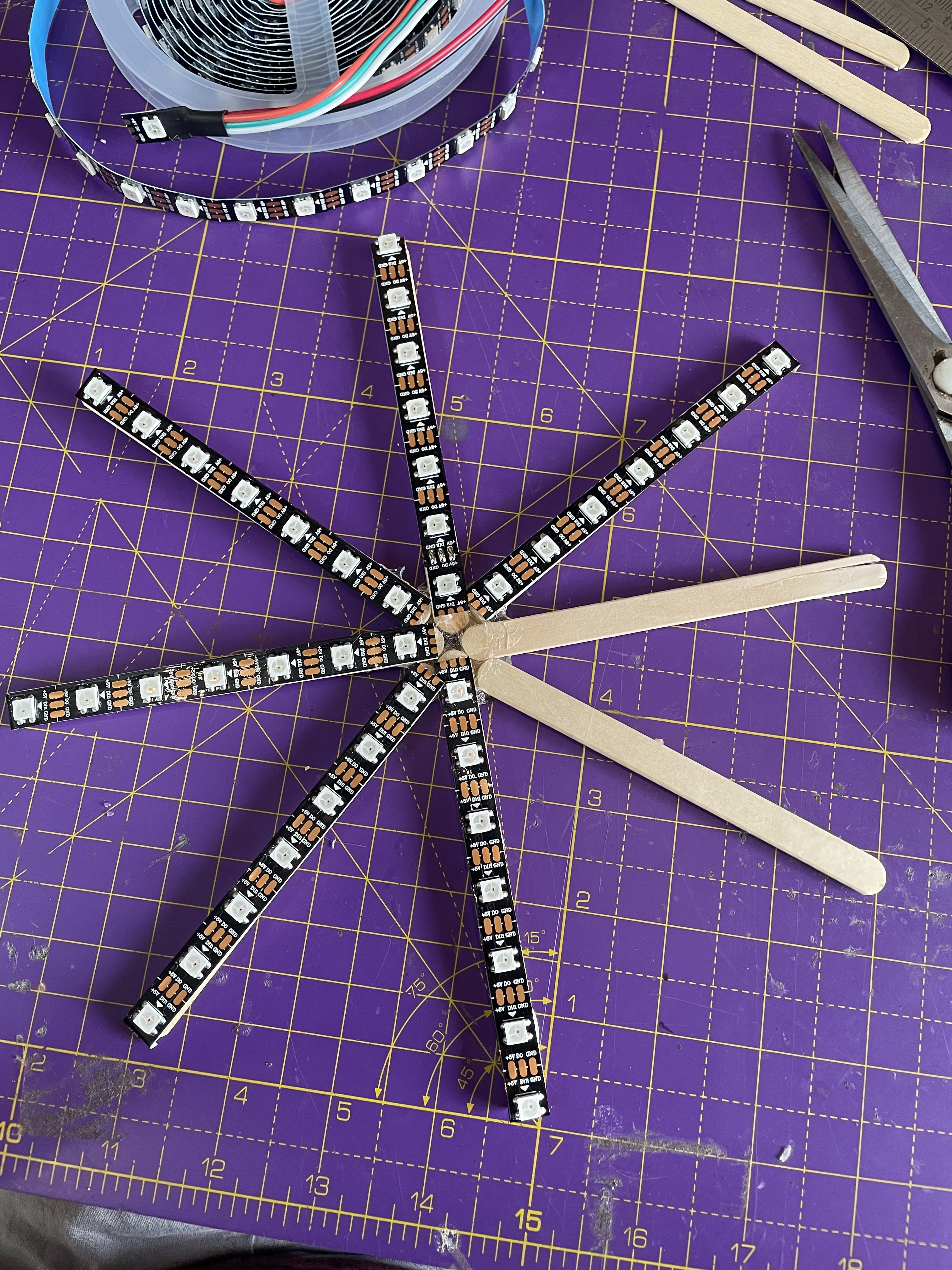
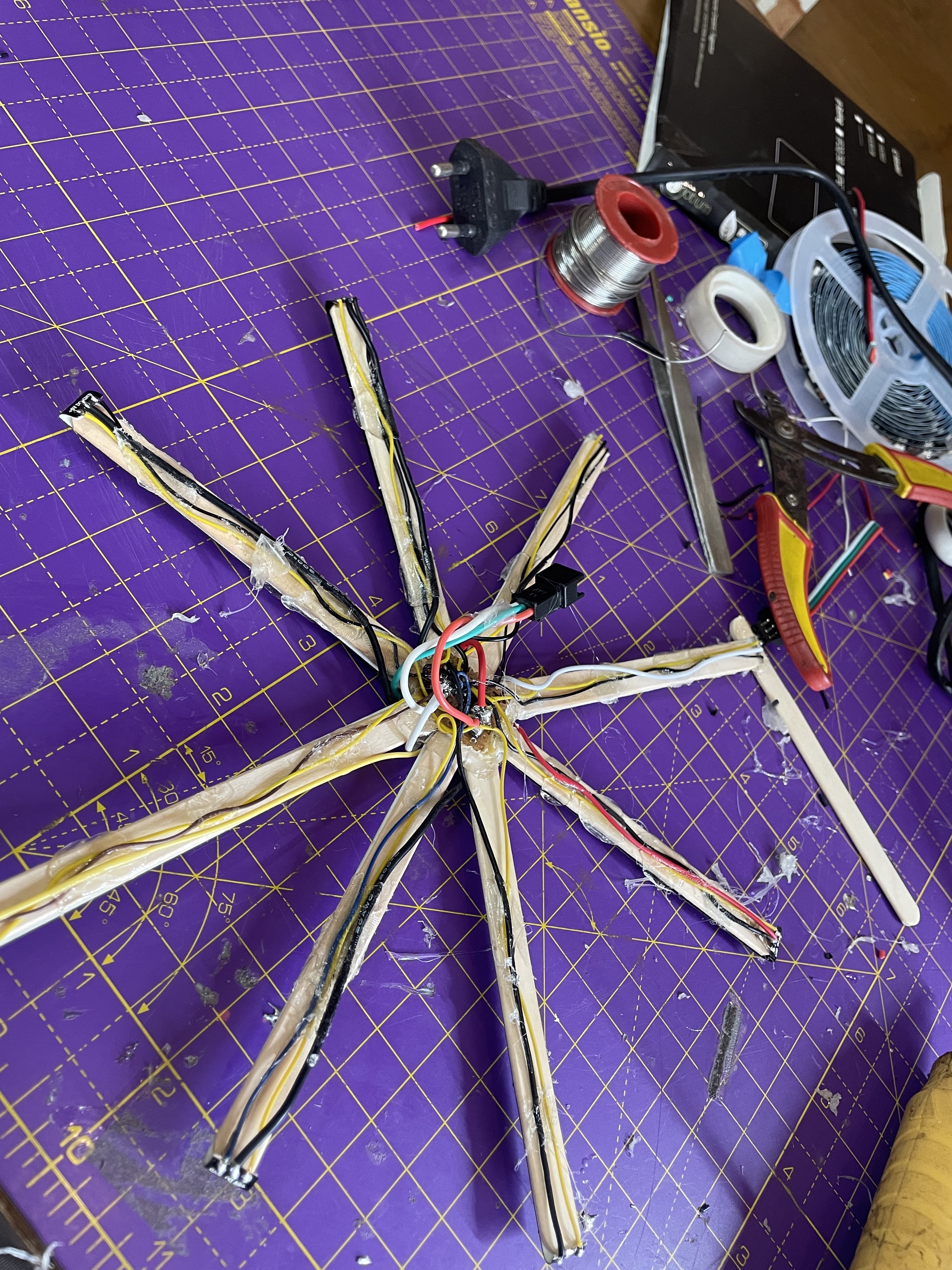
Initially I decided to 3D print holders to stick my neopixel WS82xx strip and join them together in star shape, connect it to a Raspberry Pi, and write a python script for quick sanity test of connection. However, it was taking a lot of time. So, I decided to go a bit analog and use popsicle sticks as base to stick the LED strip and just solder them together using thin wires and use glue where necessary.
Well everything worked out as planned: the base was strong and the connections were solid, but since this blog is not really about making LED star but rather interfacing balena edge device with adafruitIO, I’ll continue with that part and meanwhile, you can check out the complete build logs on balenaForums here.
So now comes the tricky part: to create a front-end and control the star remotely over the internet. Though I didn’t want a really fancy web page, just a color picker with few buttons shall do, but I didn’t want to go down that lane and write it from scratch, more so considering my JS and CSS skills are rusty since forever. There are certain services which allow you to create dashboards which can be used for the same exact purpose and today I’m gonna show you how to work with one of them and it’s really quite easy and straightforward.
Enter adafruitIO
AdafruitIO is the cloud service by adafruit industries created to talk to connected edge devices – microcontrollers and Single board computers. The communication between adafruitIO and the edge device take place over REST API or MQTT. On adafruitIO, users can create beautiful dashboards with widgets such as buttons, gauges, color wheel etc and devices can send and receive data such as sensor value to plot on the dashboard, or a soft button clicked on dashboard can be relayed to the device to take some actions.
The way it works is really intuitive. You create feeds which hold data and these feeds are associated and triggered by widgets on your dashboard. The best part is there are libraries for different programming languages making interfacing with adafruitIO extremely easy and convenient and it also manages all the authentication and connection stuff.
Let’s understand it with a simple example project – controlling a neopixel LED strip attached to a Raspberry Pi with adafruitIO.
Hardware required
- A Raspberry Pi computer
- 16GB Micro-SD Card (recommended Sandisk Extreme Pro SD cards)
- 5v WS82xx based LED strip, also known as Neopixels connected to DMA enabled pin board.D18 on RPi
- Micro-USB cable
- Power supply(s)
Software required
- A free balenaCloud account (your first ten devices are free and fully-featured, no credit card required)
- balenaEtcher to flash the OS image to your SD card
- An AdafruitIO account
- The project repo on GitHub
- balenaCLI if you’re wanting to learn how to use the command line tool and get into some advanced balena action
Step 1 : Connect the neopixel LED strip to Raspberry Pi.
Now there are a few ways to do it, some are safer than others, which may have tendency to destroy your Raspberry Pi board if not done correctly. So for connection, please follow this guide.
Step 2: Login to adafruitIO
You can use an existing adafruit account or create a new one by visiting https://io.adafruit.com.
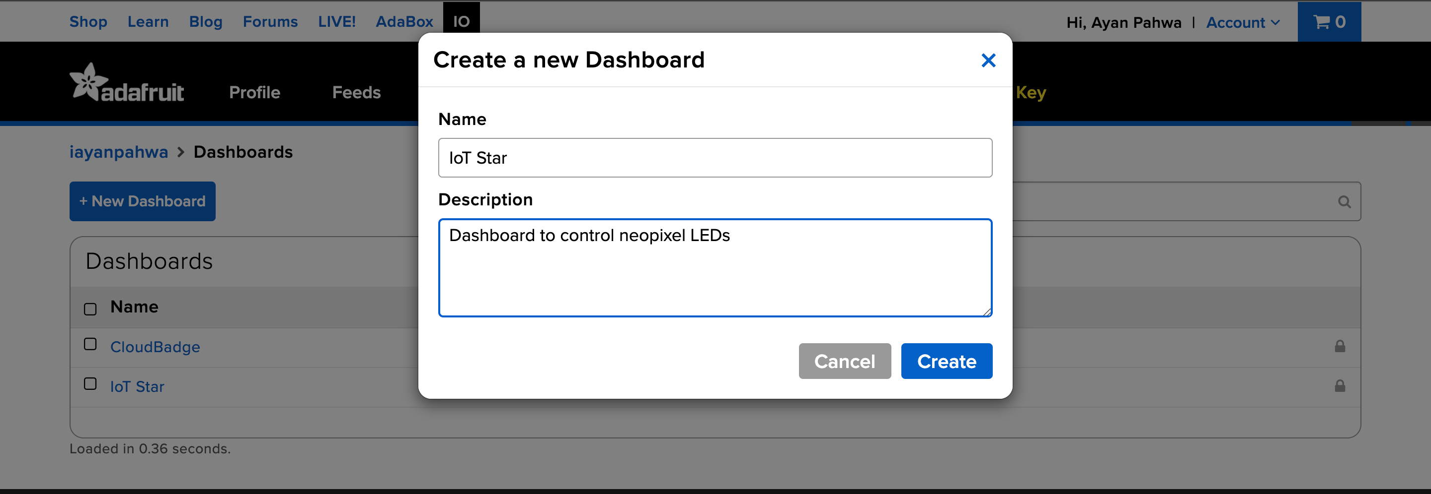
Step 3: Create a new dashboard
Next step is to create a dashboard which will contain widgets, click on dashboard > create new dashboard and give it a suitable name and description : IoT star, in my case.
Step 4: Add widget to dashboard:
Click on the gear sign and thenadd-widgets, a menu of widgets will appear which you can use, here for this project we will gonna choose a color picker, but feel free to play around and adapt as per your project.

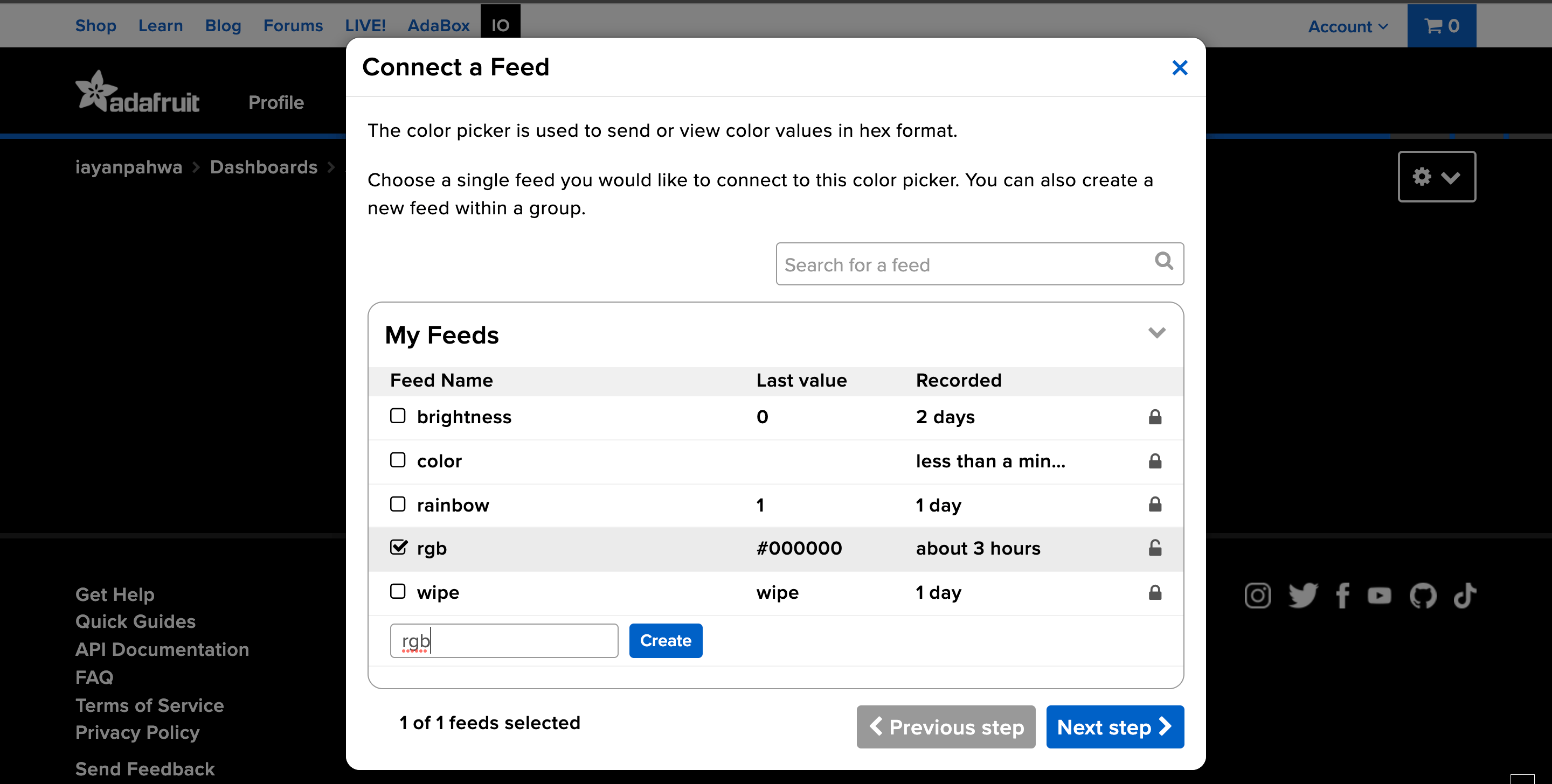
Step 5: Associate widgets with the feeds
This is an important step, as it will tell the dashboard where to send data. Since we’ll be using MQTT, the feed name will become the topic which we will subscribe to for new data/changes from our edge device. Name the feed where color picker will send color value and remember the name as we will be needing it later.
Here you can optionally add new widgets and associate them with same or different feeds, e.g. a push button can also publish 1 or 0 to RGB feed along with color picker publishing RGB values.
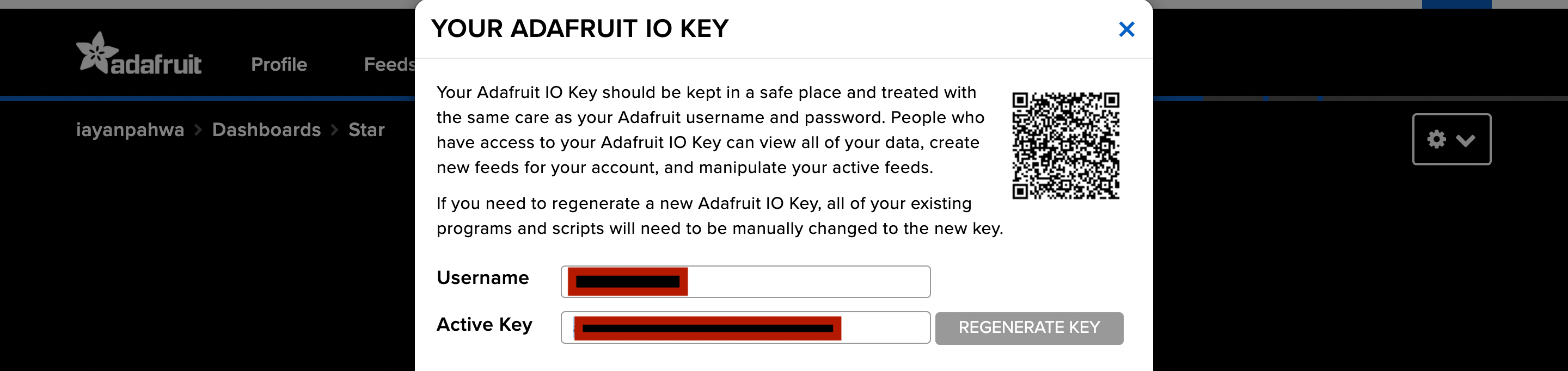
Step 6: Copy the username and active key
Click on My Key button and copy Username and Active Key. This will be used to authenticate to your adafruitIO account.
Step 7 : Deploy a sample application on Raspberry Pi device
I’ve created a sample project, which you can use to deploy on balena cloud and modify it as per your needs. You can clone the project from here and deploy it on your balenaCloud using balena push or just use deploy with balena button below:

You can also check out the GitHub repo.
Step 8 : Configure the device variables
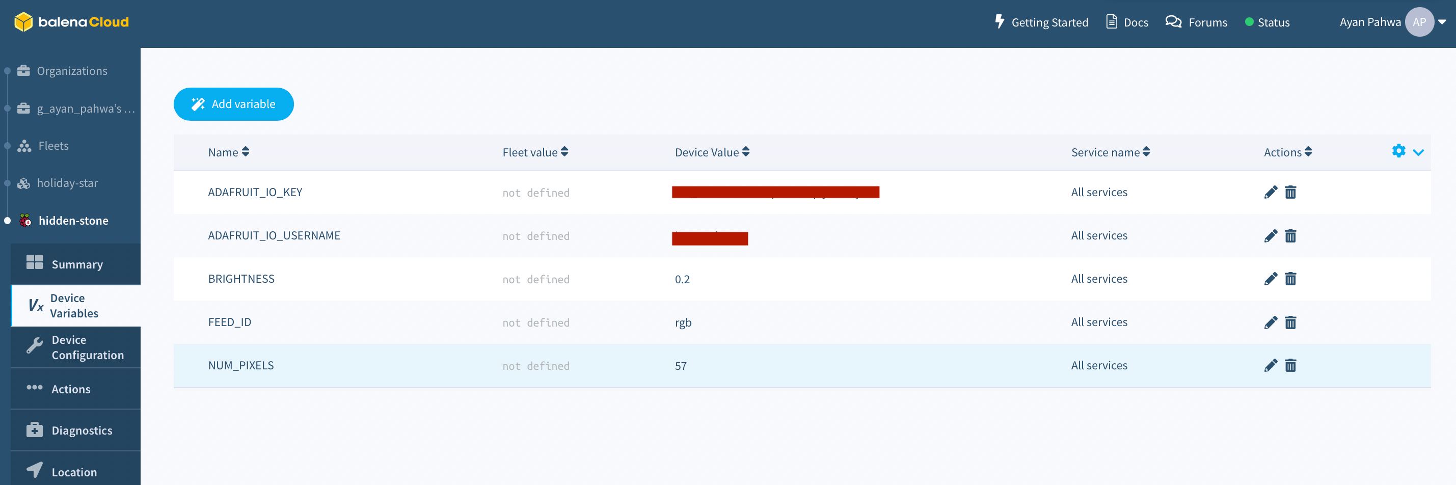
Once the fleet is deployed and main container starts working, we need to add few device variables like – the username, API key and some other parameters to make it work. On balenaCloud Dashboard under devices > device variables add the following variables:
| ENV VARIABLE | DEFAULT VALUE | POSSIBLE VALUES |
|---|---|---|
| NUM_PIXELS | 60 | This should be equal to number of LEDs in your strip |
| BRIGHTNESS | 0.3 | Any value b/w 0 and 1, more the brightness more current will be consumed. |
| ADAFRUIT_IO_KEY | N/A | Key copied from adafruitIO from step #6 |
| ADAFRUIT_IO_USERNAME | N/A | adafruitIO username copied from adafruitIO from step #6 |
| FEED_ID | rgb | Name of the feed created in step #5 |
Once you submit these changes, the main container will restart and you’re good to go. Go back to the adafruitIO dashboard and use the color picker to change color on the LED strip and it will work all in real time.
How does it work?
AdafruitIO color picker is sending the RGB value of the color we picked over MQTT under the topic
Give it a try
I hope you like this project and get a pretty good idea of how to interface a balena EDGE device with adafruitIO, this is pretty generic across different cloud services on the internet. So give it a try and do share your project with us if you do so on balenaForums, twitter or other channels mentioned down below.
As always the project is open-source, feel free to fork, make changes or contribute if you feel so, till then, keep making and let us know what you think in the comments below.
Hi Andrew, thanks for posting your project. I am developing a project using the Adafruit SCD-30, SGP30 using the SparkFun Qwiic SHIM, for temp, humidity and Co2 sensing.
Do you think your dockerfile with…
…would be enough to get them running? I am wanting to deploy them along with the Browser block and a touch screen to give a full environmental monitor.
Hello @YouGenerateCIC ,
Thanks for checking the project out. I’m going to give a shout to @iayanpahwa , the project creator, to weigh in on your question. Hang tight as he’s out for today but will be back tomorrow.
Hi @YouGenerateCIC , I think you’ll also need to install python drivers for the modules
scd30usingpip3 install adafruit-circuitpython-scd30and forsgp30usingpip3 install adafruit-circuitpython-sgp30.You docker file should look like:
Let me know if this works
Thanks @iayanpahwa for your help. Unfortunately I am still getting back:
I did test with your suggested changes to the docker file but with no luck.
To make sure I could get something working I tried to follow the sensor block setup and got the bme680 working as below.
My current sensor Dockerfile is
Should I be able to copy in the RUN commands into the sensor block docker file as above to get the correct drivers?
e.g.
Thanks
Hi @YouGenerateCIC , happy to know you were able to test with sensor-block and rule out the possibility of non-functional sensor module. As far as the dockerfile is concerned, you can only use one base image, feel free to take ideas from dockerfile of sensor block and try to create one with your packages but I won’t recommend modifying it right away as it uses custom start scripts which is not recommended to change for proper functionality.
Thanks how can I find someone to do this for me?
@YouGenerateCIC I’m not sure where you could find someone to do this for you but if you give it a shot I’m happy to help you through, working with docker is mostly a back and forth process, though I can recommend you try
local modeandlive pushdetails here to speed up your development workflowThanks @iayanpahwa learning fast!