
This post has been updated: We published a revised and simplified version of this guide (with extra features!) for December 2019 here.
Interested in building an LED lighting project with Raspberry Pi? We’ve got you covered! In this post we’re going to take a look at setting up a custom RGB LED matrix and driving it with a Raspberry Pi, Fadecandy board and Glediator software.

For the longest time I’ve been wanting to build an RGB LED lighting project for the holidays and various things would get in the way (notably, the holidays!) and I’d never get to it. Things finally worked out this year; whilst I was visiting the balena Seattle office, our CEO Alexandros mentioned he had some RGB LED strings and a nice Mean Well power supply that would be perfect for a holiday lighting project. I suspect I got far too excited about this and cracked out the soldering iron immediately to start putting things together.
My goal was to build a lighting setup that could be placed on a tree but remain addressable as if it were a conical shaped LED matrix. This meant whatever software setup I ended up with should be configurable to allow the various LED strings to be physically laid out and drivable in an order not necessarily the same as that in which they are arranged electronically.
I’ve built lighting systems and driver boards in the past that only served for the purpose of interfacing the lighting with some other control system such as a PC or laptop, either over serial (RS232/RS485) or ethernet. Whilst this setup works fine, it does introduce a dependency on a computer/server running somewhere else either within the vicinity or over the network somewhere. For this project I wanted to do things differently and build the controller unit in such a way that it was completely self-contained and would continue to operate independently of any
external control systems.
What you’ll need
There’re a few things you’re going to need to build this project:
- Some addressable 5V RGB LEDs
- Raspberry Pi 3 & SD Card
- A free balenaCloud account
- Fadecandy board
- High quality power supply (i.e. Mean Well LRS-100-5)
- Case to put everything in (or 3D printer to print one)
All the components required are discussed in more detail below.
Choosing the LEDs
Anyone who’s done some research into building LED matrices with RGB LEDs will have no doubt discovered the WS281x (and also the more recent SK6812) addressable RGB LED driver. This driver works on a 1-to-1 basis with each individual LED and is externally attached or, in the case of some newer matrices, built into the LED itself. These driver integrated circuits (ICs) have become somewhat ubiquitous over recent years and are now easily obtained attached to a variety of different LED arrangements, such as strings, ribbons, rings, matrices and as individual LEDs.

If we’re dressing a tree in the traditional way, the only arrangement that really works is the ‘fairy-light’ style string; that is LEDs spaced evenly along a cable, meaning they’re fully flexible and can be draped over anything. Depending on your setup you might also be able to use the ribbon/strip type arrangements, which are also flexible, but not in all directions.
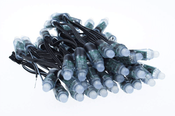
As with the other form factors, these are easily available, but with a small catch; the strings generally have a multi-colored cable which works fine in some applications but not so well in others (such as dressing a tree). They are available with single colored black or very dark green cable which is perfect, but can be harder and/or more expensive to obtain like this. The easiest way to get hold of some would be to check out the usual suspects, such as Amazon and AliExpress. Make note of the voltage of the LEDs you obtain (I’m using 5V) as it will change some other parts of the setup. A good search term to try is “RGB LED addressable”. Here’re a few links to get you started:
As an aside, there are some other terms that are commonly used when referring to this stuff. Firstly, the term ‘pixel’ when applied here refers to a single RGB LED with the accompanying driver IC. Secondly, ‘neopixel’ is a term coined by Adafruit which essentially means the same thing and is used to refer to their (very cool!) line of products that use these LEDs and drivers.
Driver hardware

As the LED driver ICs that we’re using are so prevalent, there are a wide variety of options for driving them. There are a lot of libraries out there that enable the use of them on various different platforms, alongside APIs and bindings to a number of different programming languages, so you can for the most part choose one that fits your experience and knowledge.
The one thing to note about these drivers is that they have quite precise timing requirements. Whilst this is not a problem due to the wide variety of open source libraries that are available, it does mean if there is any interruption in the execution of that code (for example, a CPU becomes busy with another task), you’re going to see glitches in the output. Given that the output is highly visual and needs to look great, we want to avoid this!
If you’re interested and want to learn more, there’s a really great article which goes into great detail about the timing aspects of these pixels on josh.com.
This is why you’ll find a lot of the libraries are written for microcontrollers where they can be sure of timing, rather than fully fledged operating systems such as those that are used on the Raspberry Pi. Whilst it is perfectly possible to drive the LEDs directly from the GPIO pins from the Raspberry Pi, they are subject to interference whilst the CPU services other processes. To circumvent this, we can use the Raspberry Pi to handle the control side of things and hand the task of dealing with the timing off to a separate microcontroller-based driver board.
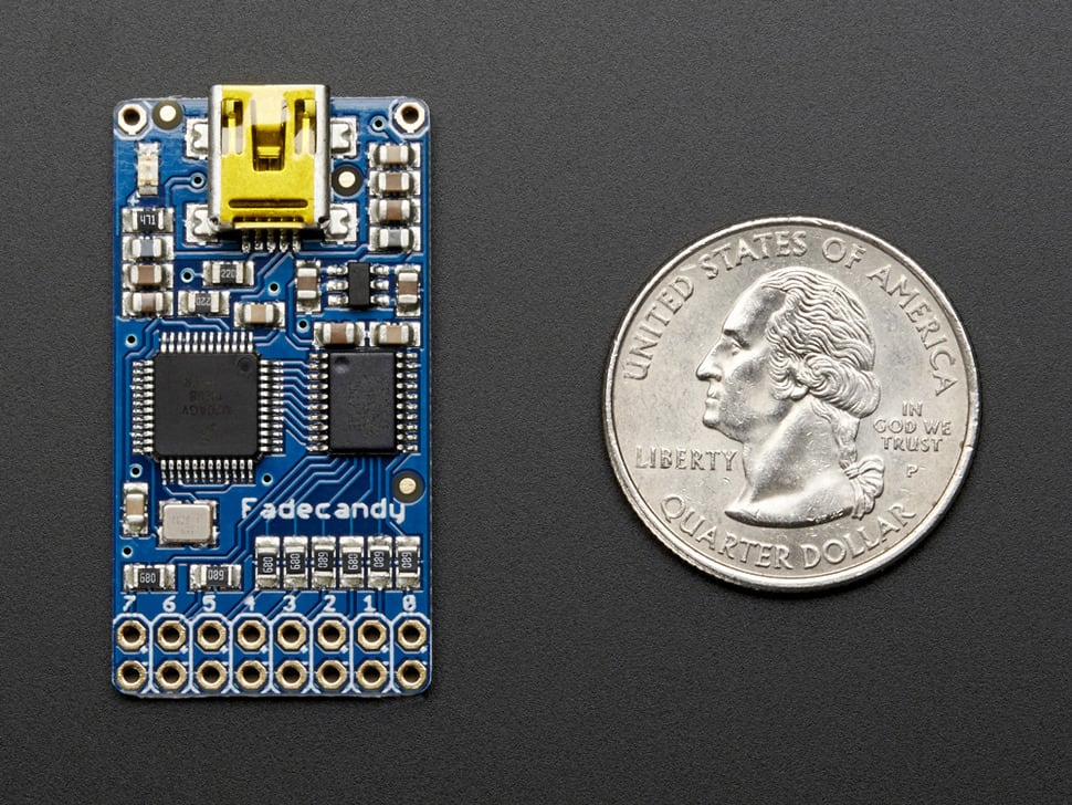
The board I decided to use in this instance is Adafruit and scanlime’s collaboration: Fadecandy. This board implements the Open Pixel Control (OPC) protocol for communication, which means any software that can communicate using this protocol will work with the project. In addition to standardising on communication protocol, the board handles the timing and dithering which makes things look really smooth. It provides 8 channels which can each handle upto 64 pixels, for 512 pixels total capacity per board (you can run multiple boards too, if required). If you’re in the UK/EU they’re available at PiSupply, otherwise they’re available directly from Adafruit. It’s really a very advanced board which implements a lot of techniques to make these LEDs look their best; read more about it on the Fadecandy GitHub repo.
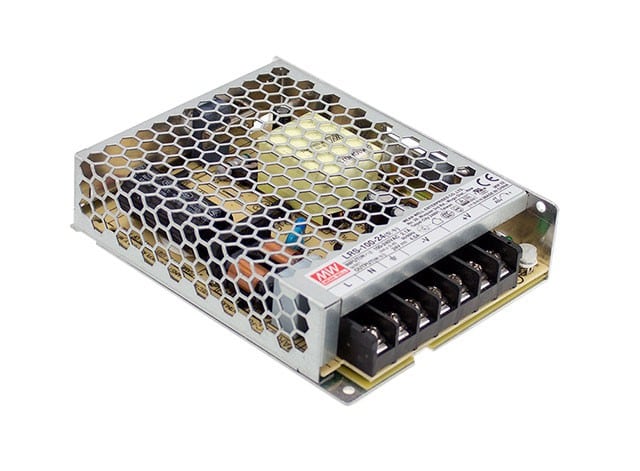
The third major component needed to complete the setup is a good quality power supply unit (PSU). From experimentation, I found that the pixels demand good, clean power; which means a stable voltage and capability to meet the changing current demands as different pixels and colors are lit. Without this, I found interference to be more common towards the end of strings. I chose a Mean Well PSU, as they have a reputation for good quality and are easily available from the usual electronics suppliers (e.g. Mouser) as well as the more generic ones such as Amazon. If you use 5V LED strings, then the same power supply can power the Raspberry Pi, too. Specifically, the unit I chose was a LRS-100-5, which is a 5V supply capable of delivering 18A.
We need a housing to keep everything together safely, as parts of the setup will be operating at mains voltage. Given that the electronics will likely be situated in the living room and accessible to the whole family, including children and pets, it’s important that we make it safe to be around.
Software plan
We’ve decided upon our LEDs, along with a power supply, a Raspberry Pi, and a means to interface with them. Time to think about software!
As discussed in the hardware section above, I’m using the Fadecandy board for this project, which has associated server software that receives the OPC messages over the network on a TCP port and sends the appropriate control messages via USB to the board. That’s one part of the system taken care of, so we now need something that generates OPC messages to feed Fadecandy.
In addition to providing the server software, the creators of Fadecandy also provide libraries and examples in various different programming languages demonstrating how to communicate using OPC. The server software along with all these examples can be found in the Fadecandy GitHub repo.
If you’re planning on writing your own software to generate patterns for the LEDs, or even modifying and using the example projects, you don’t need much more, other than the environment for your chosen language to be setup and working. I wanted to take things a little bit further and set things up so I could use the Glediator application, which offers a full-fledged GUI for creating and scheduling animations to run on your matrix.

The use of this software introduces a couple of extra challenges. First, it’s a GUI application, so in order to maintain the requirement of running everything on the Raspberry Pi and keep it self-contained, we need to setup a virtual X server as well as configure a VNC server to access this remotely. Second, Glediator does not communicate in OPC but instead uses a protocol called ArtNet. Not only do we need to perform a translation from ArtNet to OPC, but we also need to work around the 512 channel per universe limitation it has, and remap the channels to the layout used on the tree. To explain; we’re using one channel per color, so each RGB pixel uses 3 channels. Unless you’re using less than 170 LEDs, the matrix will span multiple universes (and let’s face it, a mere 170 LEDs is never enough!).
Based on this there are 3 software components to consider and set up:
- Fadecandy server (fcserver)
- ArtNet translation
- Glediator (including X and VNC servers)

The project will be deployed to the Raspberry Pi using Docker containers via balenaCloud, and the 3 components above fit nicely into one container each. Furthermore, this setup will facilitate the development of your own code, by disabling the ArtNet and Glediator containers and adding your own container to communicate with fcserver in their place.
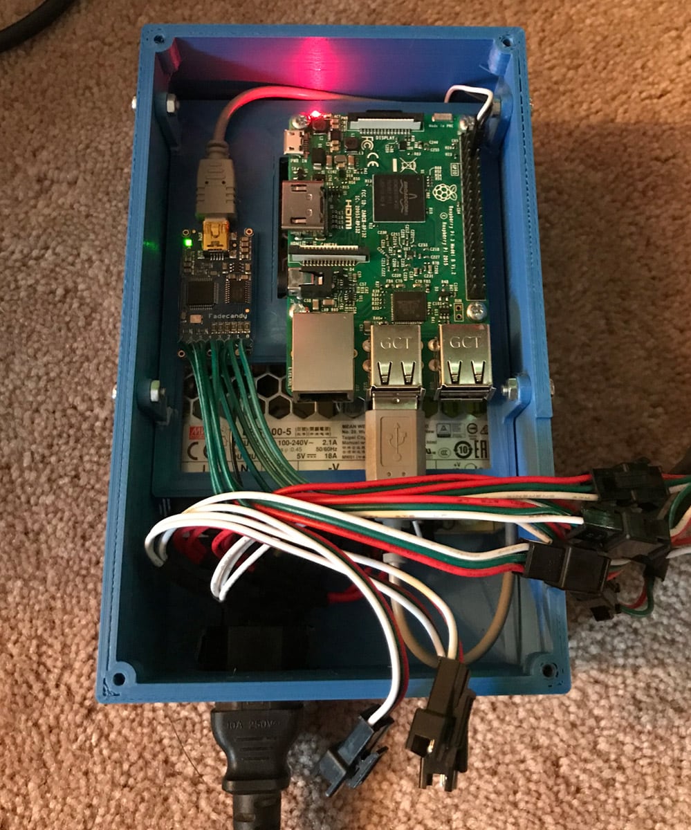
Assembling the hardware
The hardware is very simple to assemble, we have to connect the LED strings to the Fadecandy board and the PSU, connect the Fadecandy to the Raspberry Pi, and connect the Raspberry Pi to power (luckily, as we’re using 5V LEDs we have a really nice 5V PSU which is ideal for powering a Raspberry Pi!).
Case
Earlier, we discussed the requirement for all the components to be safely housed due to their siting in a living room, possibly accessible by other family members, young children and pets. Given that we’re dealing with a mains voltage supply to the PSU, it’s important that this is made safe. Therefore I’ve designed a custom case which can be 3D printed, designed specifically to house the components we’re using. The design was produced using Autodesk Fusion 360 – a great (and free if you’re a startup or hobbyist) all-round package for 3D CAD/CAM.
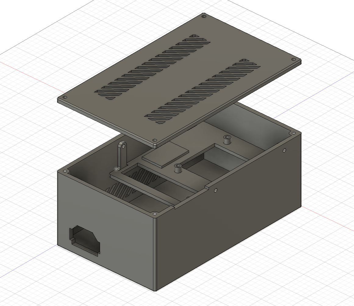
I printed mine on an Ender 3, and I’ve published our design on Thingiverse so you can print your own. The 4 holes for the lid are threaded M3, and the 4 holes for mounting the Pi are sized for M3 clearance (3.4mm), as I generally like to enlarge the mounting holes in the Pi to use M3 hardware.

There’s a small cutout in the top edge of the case, and a corresponding one in the lid to allow the cables for the LED strings to emerge. A further development would be to employ some form of case mount connector system to make things a bit more robust, but the current solution is good enough for now.
Power supply
The power supply is mounted in the bottom of the case, and connected to the mains power supply via means of a panel-mount IEC C14 connector. The connector I used was a snap-in kind with the clips on the left and right and so there are cut-outs in the case design for this. Alternatively, you could drill the case and use a flange mount type with screw fixings.

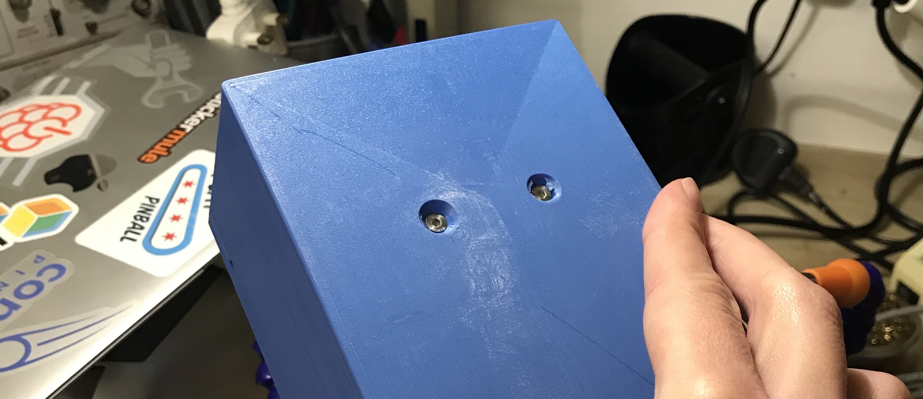
The case has two holes in the base which are designed to align with the mounting holes in the LRS-100-5 PSU, in which you can use a couple of countersunk M3 machine screws.
Once the power supply and the IEC connector are mounted in the case, the three connections need to be made for live (hot), neutral and earth (ground), in the usual manner in order to connect it to the mains supply.
Fadecandy board
The Fadecandy board is very small and has no mounting holes, and so I opted to mount it to the tray in the case with double-sided adhesive carpet tape. For this reason the tray includes a small, raised platform to provide space for the soldered connections at the edge of the board.
The board has two rows of 8 connections, one of which is the data line for each channel, and so each channel is connected to each of the LED strings. The other row of connections is for ground; we need to connect one of these to the PSU. Although the board is technically grounded via the USB connector, in my experience, this wasn’t sufficient and caused some interference when adding more than 200 pixels; once the ground connection was made directly to the PSU, though, everything worked fine.
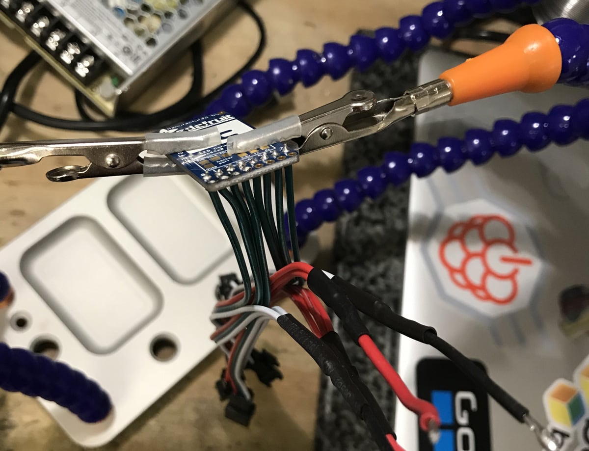
To make the setup modular, I opted to solder small tails with the correct (3-pin JST SM) connector to the board, allowing all or individual channels to be connected or disconnected at will. You should be able to obtain a pack of these tails from the same suppliers as the LEDs, here’s an example on Amazon.
As you can see in the above image, the green wire from each table is soldered to the corresponding channel on the Fadecandy board, whilst all the white and red connections are grouped together ready for connection to the PSU.

Raspberry Pi
The Raspberry Pi is mounted onto the 3D printed tray using M3 machine screws and nuts. In my case I have enlarged the holes in the PCB of the Pi to accept M3 hardware as I had nothing smaller on hand. If you don’t want to drill the holes out in your Pi (which is perfectly understandable!) you’ll have to find some M2.5 mounting hardware to use, which will fit without drilling.
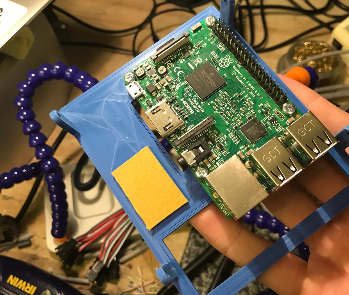
The only connections required to the Pi are a +5V and ground to the PSU, and a USB connection to the Fadecandy board. This cable needs to be USB A to mini-B (as opposed to micro as used on the Pi).
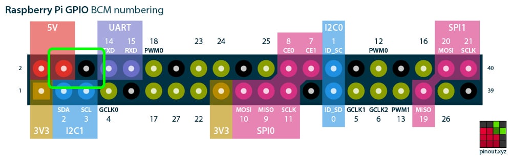
The PSU can be connected directly to the power pins on the GPIO header using male-female dupont cables, saving the need for another USB cable to be crammed into the case.
Extension cables
Depending on your setup, you may find that you need some extension cables so that the LED strings can start a certain distance away from the Fadecandy board rather than right next to it. I created a 2 metre extension for each string using some spare CAT5e ethernet cable and some more of the 3-pin JST SM tails the same as those soldered onto the Fadecandy board.

LED strings
After everything is ready, the final part of the hardware assembly is to connect the LED strings to the tails you’ve soldered onto the Fadecandy board. The strings should be connected starting at channel 0 and working upwards. It is technically not important where they are connected as we are able to map things in software and cater for any configuration, but it will make things easier for us when setting up and addressing the matrix in software if they are in order.
Lighting up the tree
The LEDs need to be laid out on the tree in such a manner that we can configure the software with their location. I opted to run each string from the top of the tree to the bottom and back up again, meaning that with a string of 50 LEDs that gave me two columns of 25. This was then repeated for 5 strings, effectively giving me a matrix of 25 rows and 10 columns. The diagram shows how the LEDs were arranged on the tree, which leads into how the software is configured later on. The numbers relate to the LED number in the chain, starting from zero.

To achieve this meant that almost the full 2 metre extension cable that I made for each string was used in the process of locating the start of the LED string at the top of the tree. The completed box of hardware now sits at the base of the tree; who could ask for a better gift?

Setting up the software
As mentioned previously, the software for this project is going to be deployed with Docker containers using balenaCloud.
I’ve put my entire software configuration on GitHub to get you up and running really quickly, but if your matrix configuration is not exactly the same as mine, there’s going to be a bit of configuration you’ll have to do to in order to get started.
If you’ve done this before, here’s the repo, otherwise read on for some more detailed instructions.
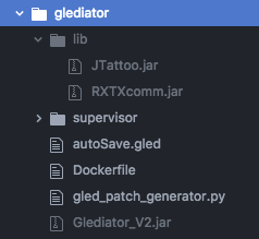
Note: The Glediator software is not included in the repository; it must be downloaded from the Solderlab website and added to the project directory before you push everything to the Raspberry Pi. Once you’ve cloned our repo, add Glediator_V2.jar and the associated lib folder to the root of the glediator folder in the project; your folder should then look like the below:
balenaCloud
The first thing to do is to get set up with a balenaCloud account; this means signing up if you haven’t already, adding an application and adding a device.
Step 1 – Sign up to balenaCloud
The first thing you’ll need to do is sign up for an account. If you’ve already got a GitHub or Google account you can use that to login and bypass the signup process.
Step 2 – Create an application
Add an application using Raspberry Pi 3 as the default device type, and choosing Starter as the application type, then hit Create New Application.
This will take you to the dashboard for your newly created application, where you can move on to the next step and add your device.
Step 3 – Add a device and download the OS
Once your application has been created, you can setup and add a device within that application by clicking the ‘add device’ button. When you add a device you specify your device type, which in this case is a Raspberry Pi 3, and if you are connecting to a wireless network you can set your WiFI SSID and passphrase here too.

This process creates a customized image configured for your application and device type, and includes your network settings if you specified them.
Note: When you’re first getting started, a development image will be most useful, as it permits a number of testing and troubleshooting features. More details on the differences between development and production images can be found here.
Step 4 – Flash your SD card and boot the device
Once the OS image has been downloaded, it’s time to flash your SD card. You can use balenaEtcher for this.
Once the flashing process has completed, insert your SD card into the Raspberry Pi and connect the power supply.

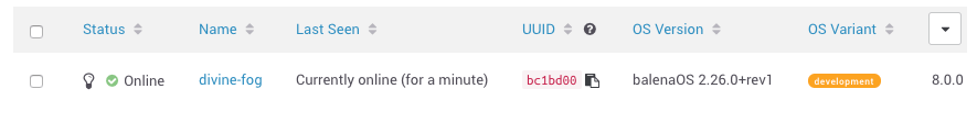
When the device boots for the first time, it connects to the dashboard, after which you’ll be able to see it listed as online and move onto the next step.
Troubleshooting: It should only take a few minutes for the new device to appear in your dashboard, If your device still hasn’t shown up on your dashboard after a few minutes, something has gone wrong. There’s an extensive troubleshooting guide in the documentation, with lots of information on why this could be, but if you still can’t get your device online, come on over to the forums where we’ll be able to help out.
Step 5 – Deploying code
Now that your Raspberry Pi has been provisioned, has booted, and connected to balenaCloud, you’re ready to push the application code to the device.
Installing the balena CLI tools
If you already have (or can setup) npm on your machine, this is most likely the easiest way to get the CLI tools up and running quickly. However, there are also standalone binaries for Windows, macOS and Linux available.
The documentation for the CLI tools is the best place to start, and covers the installation and setup of both the npm package and the standalone binaries.
When you have the CLI installed and working, the first step is to login to balenaCloud by issuing the balena login command:
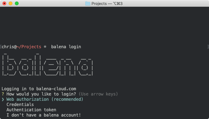

Once you’ve reached this point, and have a working CLI which has been logged in to your account, you’re ready to start pushing code to your Raspberry Pi.
Downloading the project from Github
The next step is to download the code for this project from GitHub. Go to: https://github.com/balena-io-playground/fadecandy-led-controller and download the project.
The blue button will download a .zip file of the project but if you’re already familiar with Git you can use git clone in the normal way.
Pushing the project code to your Raspberry Pi
As you have the CLI setup and the latest code downloaded, you can now execute a single command to push that code to balenaCloud which in turn builds the Docker image and handles the process of setting it up and running it on your device.
From within the project directory, execute balena push <appName>, where appName is the application name you set back at the beginning of the guide. For example: balena push fadecandyXmas.
If everything worked out correctly, after a few minutes your device information screen in the dashboard should look something like this, showing the 3 services running, one for each of the software components.
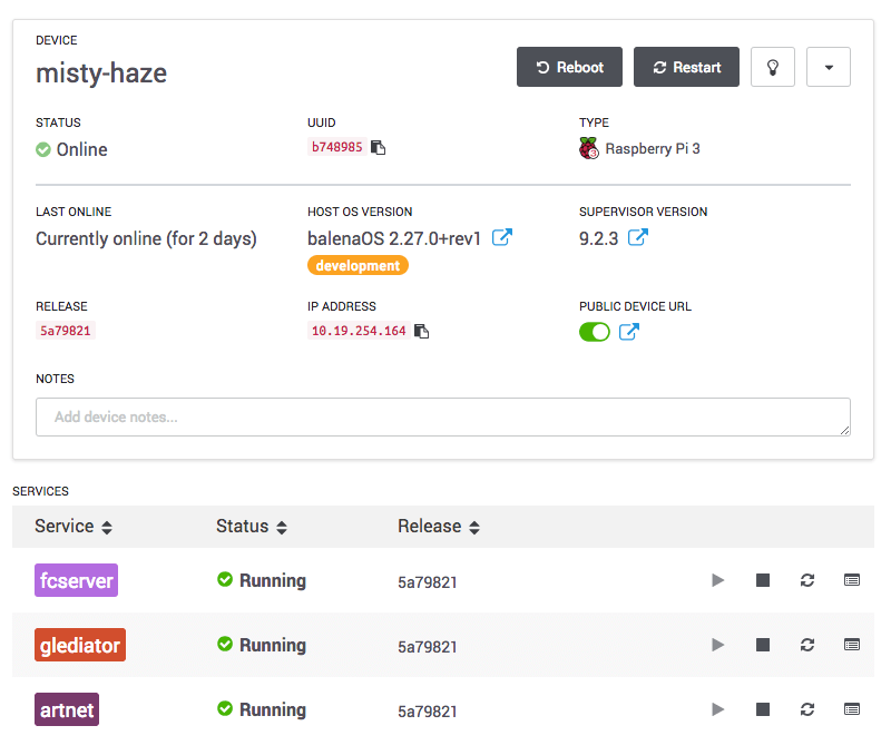
When you push the code for the first time it can take a few minutes to download (dependant on your internet connection speed) but after that only the changes in the container are downloaded so things happen much quicker.
The configuration for each service has been built in such a manner that they are all preconfigured to connect to each other via static IP addresses. If your setup is an exact replica of mine, everything should be ready to go out the box, otherwise read on to find out what changes you’ll need to make to get things working.
Fadecandy/fcserver
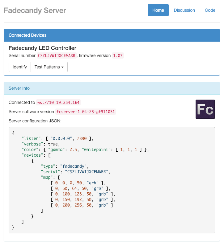
You should now be able to access the Fadecandy web interface by browsing to the local IP address of your device. You can find it in the balenaCloud dashboard on the device information page. For example, in the case of my device above, I would point my browser to https://10.19.254.164 and see something like the below:

You’ll note that it says no devices connected, even though you’ve got the Fadecandy board connected. What gives? In order for the software to detect and start using your device, it needs to be configured with the serial number of your device rather than mine.
In order to do this, edit the file named server.json within the fcserver project directory. The easiest way to obtain your serial number (as long as the board is detected by the Raspberry Pi) is from within the balenaCloud dashboard. If you take a look at the logs, you should see that when fcserver starts up, it detects the device but does not use it due to it being missing from the configuration. For example:

Copy and paste the serial number from this log into server.json, replacing the serial number that’s in there already.
Here too is the place where you can specify your LED configuration. If you don’t have 5 strings, you can add or remove rows depending on if you have more or less LED strings. I recommend taking a look at the fcserver documentation if you’d like to fully understand how the configuration works here, but essentially it’s creating a map of pixels in the OPC protocol to how they are connected physically and electrically. For example, 0, 50, 64, 50, “grb” means we are mapping OPC channel 0 pixels, starting at OPC number 50, to Fadecandy pixels starting at number 64 (because this line relates to channel 1, and there are 64 pixels per channel on the Fadecandy side) and that we’re mapping 50 pixels in this configuration line. ”grb” refers to the order in which the colors are sent to the pixels, which may differ in your situation. The mapping is necessary in this case as we are only using 50 of the available 64 pixels on each Fadecandy channel; if you were able to obtain (or build) strings of 64 pixels this would all be dealt with automatically.
Push the code again, the same way you did previously. After the container has been built and the device updated, which will take a minute or so, refreshing the web interface for Fadecandy should give you something like the following:
You can use the test patterns facility here to check your controller and LEDs are all working correctly. If you can successfully turn on your LED strings using the “full brightness” command in this menu, we’re ready to move on to the next step.
ArtNet
The ArtNet container runs a Python script that serves the purpose of translating the received UDP ArtNet messages into OPC messages and sending them over a TCP connection to the Fadecandy server.
The Python script within this container is largely based from the work by GitHub user chunk100, in their Glediator-with-Fadecandy project, but has been modified to deal with multiple OPC universes; as discussed earlier we need to do this as we’re working with more channels than the single-universe limitation of 512.
In addition to the translation of the messages, this script is also handling the matrix mapping, where we are taking the regularly ordered matrix layout in Glediator, and mapping it to the irregular layout of the tree. If your matrix layout is not the same as mine, you’ll need to make some changes in the script at `artnet/src/artnet-server_fc.py’.
The main thing to consider here is the array mapping. Looking at the gridarray you’ll note that the numbers increment in a zig-zag pattern up and down from left to right, counting up to 25 on each column. This is a direct correlation to the LEDs as they are laid out on the tree, and corresponds to the diagram of the tree we looked at earlier.
If you change the size of your matrix, you’ll have to update the variables as appropriate, maintaining the fact that we have a universe limitation of 170 pixels.
Note: it’s possible to configure Glediator to handle the matrix mapping as well, meaning it could be removed from this component and simplified. When the patch file is generated it would be straightforward to apply the transformation there; this is something I’ll be working on in the future!
Glediator
Now it’s time for the fun stuff! We can finally start to configure the output that’s going to run on the matrix. Glediator is an awesome bit of free software built to produce animations for LED matrices.
Glediator is a GUI application, and as we discussed earlier, we wanted to run everything required for this project on the Raspberry Pi to keep it self contained and not rely on any other external computers or services to run the lighting installation. To achieve this, Xvfb has been installed and setup with a VNC server as part of the container setup, which means to see and work with the Glediator GUI, you can connect to the Raspberry Pi with a VNC client.
The container has been configured to expose the standard VNC port (TCP 5900), and so if everything is working correctly, you’ll be able to connect to the Raspberry Pi on the local IP address with a VNC client. Take a look at RealVNC Viewer (fully cross-platform) if you don’t have one already.
Note: The VNC server has been configured without a password, and is not encrypted! If you need to set this up, take a look at the x11vnc documentation, along with the service configuration in glediator/supervisor/conf.d/x11vnc.conf.
Starting the output
The output will not start automatically! As far as I can tell, Glediator does not offer any facility to start the ArtNet output automatically when the program starts.
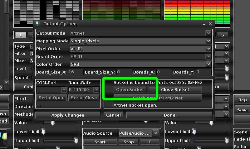
If your setup is the same as mine, the default configuration I’ve included in the software setup will work, and so you’ll need to open the socket to start the output. This is done via Options > Output and then by clicking Open Socket as pictured above.
Customizing the setup
If you do need to make changes to my configuration to fit your matrix, there are a couple of things we need to do in Glediator. You can make these within the GUI itself but I’ve also created a patch generator script in Python to make this a bit easier.
I am assuming that the thing most likely to change is the matrix size. At the moment, as the mapping is dealt with during the ArtNet translation, we only have to change the dimensions of the matrix and reapply the new patch.
To help with this, I’ve created a script that generates a patch file that can be loaded by Glediator. The script is glediator/gled_patch_generator.py and has a few customizable options at the top of the file.

You can see that this has been set up for my matrix in it’s 10×25 configuration as described earlier. When the Glediator container starts up, this patch generator script is automatically run and creates a file called patch.gled within the container at /usr/src/app/patch.gled.
For Glediator to be able to import this patch file, the matrix size within the application must match that which you’ve set. This can be changed via the Options > Matrix Size menu:

After this has been set correctly, you can load the patch file. This is achieved via Options > Output, and then clicking Patch Artnet/TPM2.Net, and then loading the file:

After this you’re hopefully fully up and running and free to have a play with the settings in Glediator to create different patterns!
Programming examples
If you’ve got everything up and running with Glediator and want an additional challenge, or just don’t feel like using that software and immediately want to get stuck into creating your own, good news! With everything described above, you’ve got a lot of options for programming.
The configuration I’ve shared exposes the OPC port on port 80 (note this is a change from the default 7890), and so you can make connections to that using the local IP address of the Raspberry Pi, found in your balenaCloud dashboard, from any other computer on the local network.
The Fadecandy server offers the facility to make direct OPC connections and start sending in that format, and the Fadecandy repo has a lot of examples in different languages, as does the openpixelcontrol repo.
To get started, try the examples in the above repositories. For the most part, all you’ll need to do to get them running is to update the address of the Fadecandy server in each.
Conclusion
I’m really pleased with the results of this project. It’s the best looking festive lighting we’ve ever had in our house! The Fadecandy board works beautifully, and the full software stack along with Glediator have been perfectly reliable.
When starting out with these LEDs, the amount of different options that can be used for driving them was a little overwhelming, but I’m happy with the chosen components as they’ve provided a lot of flexibility to create the light show I wanted.
There are certainly some improvements that can be made to the setup described here. Notably, the discussed improvements to the ArtNet translation setup, and relocation of the matrix mapping to Glediator via a more feature-rich patch generation script.
I’m planning on doing further work with the same LEDs, perhaps to build a giant matrix in a more traditional form factor, but that’s a job for next year, after the tree has been taken down!
Thanks for following this project through to the end! We hope you enjoyed learning about all the different software options and fun things you can do with these RGB LEDs. If you’ve set up your own project, or have any questions or suggestions for what we could do with them next, we’d love to see you in our forums. You can find us on Twitter, Instagram and Facebook too.