
With many people now working from home due to recent events, it would be useful to have a device that alerts household members when we are on a call, in a meeting, or are otherwise preoccupied. In this tutorial we will build a web-controlled set of LEDs that you can use whenever you need to send a visual signal of your availability to someone in the next room (or on the other side of the world).

We’ll set up a secure, public URL to control our LEDs, without the need to make any adjustments to our router or set up a dynamic DNS service. We’ll also configure our LED Alerter with custom button labels and device name, without the need to edit any code or files, although everything is open source so you can dive in if you want to!
The circuitry is fairly straightforward, and we’ll look at a few different builds from the elaborate to the simplistic– none of which require any soldering! Don’t let all the build steps scare you, the “easy build” is indeed very easy.
Contents
Before you start
Tutorial
Using the LED Alerter
Introduction
One of the first lessons often provided to those learning about the Raspberry Pi is how to blink an LED by programming the device’s GPIO pins. We’re going to take this simple idea, multiply it by three different colored LEDs (and an optional buzzer) and use an attractive web interface to control everything.
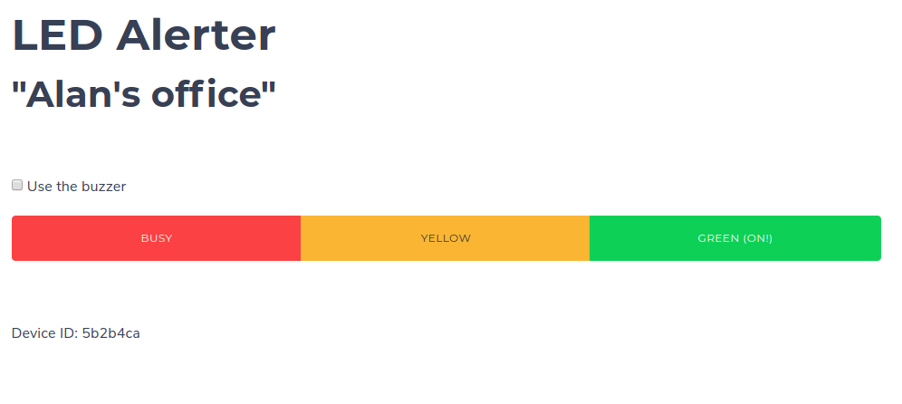
You can then place the device in any location with power and internet access, and log into its self-hosted web page to change the LED status by simply clicking a button. This is one of the powerful features of our LED Alerter. If you can reach the web page, you can change the LEDs no matter where your device is located. The button labels and the device name are also easily customizable.
There are three ways to build this project: an elaborate, ambitious big build, a simpler version, and a tinkerer’s build (where you can modify to your heart’s content). Enjoy!
Hardware Required
An elaborate build
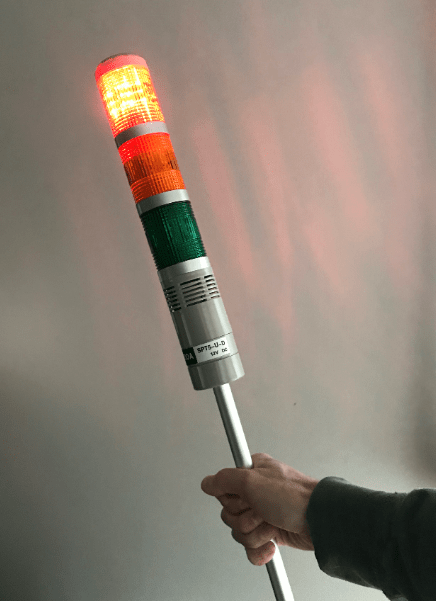
To create a real attention-getter, you’ll want to acquire one of these industrial LED towers as your signalling device. They range in price from $20 to $35 dollars and usually include an integrated buzzer. To be consistent with the parts below, make sure you get a 12V DC tower.
Here are a couple of examples:
- Adafruit
- Amazon
- AliExpress
(Note that you can use any 12VDC LEDs in place of the tower if necessary.)
Here is the remainder of the parts list:
- A 5V 4 channel relay board or HAT: (Amazon), another on (Amazon), or this (AliExpress).
- A 12V 3A DC power supply (Amazon)
- A “female DC barrel connector” with screw terminals, if not included with power supply: (AdaFruit), (AliExpress)
- A 12V DC/DC power converter with micro USB connector: (AliExpress), (Amazon) Or USB-C for the Pi4
- Dupont cables aka “Jumper Jerky” for wiring
- Optional but recommended: Two position terminal block or barrier strip (Amazon) or Wago connectors
Finally, we’ll need a Raspberry Pi, preferably with WiFi. The Pi Zero WH is recommended, but this project will work well with any model per the table below:
| Raspberry Pi Model(s) | Suitability/notes |
|---|---|
| Pi 1 (any model) | No WiFi, use Ethernet or USB WiFi dongle |
| Pi 2 | No WiFi, use Ethernet or USB WiFi dongle |
| Pi Zero | No WiFi, use a USB WiFi dongle. No header, soldering required. |
| Pi Zero W | No header, soldering required |
| Pi Zero WH | Recommended due to small size |
| Pi 3, Pi 4 (any model) | Suitable |
Also don’t forget an SD card; 8GB or larger should be fine. We recommend a Sandisk Extreme Pro.
A simple build
If you’re looking for a less elaborate build you can find HATs for the Raspberry Pi that contain three LEDs (and sometimes a buzzer!) such as this, this, or this. While the hardware construction is reduced to one step, the tradeoff is a less visible display.
You’ll also need a Raspberry Pi that is compatible with whatever HAT you choose along with an SD card and 5V micro USB (or USB C for Pi 4) power supply.
Tinkerer build
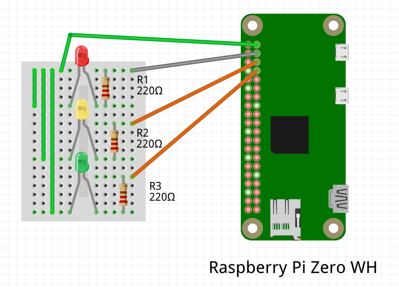
For those that have spare parts lying around, you could build this project on a breadboard with:
- Three LEDs, preferably red green and yellow, but any color will work
- Three 200 – 1000 (1k) ohm resistors
- A Raspberry Pi per the table above, along with a 5V micro USB (or USB C for Pi 4) power supply and SD card
- Dupont cables aka “Jumper Jerky” for wiring
Software required
This project has been built to run in a Docker container on balenaCloud, so you can deploy it in only a few steps as outlined below.
- A download of the project from GitHub
- Software to flash the SD card (balenaEtcher)
- A free balenaCloud account to set up and manage the Pi
- A download and installation of the balenaCLI to be installed on your development computer used to push code to the cloud
Set up the hardware
If you opted for the easier build, your setup is simply to attach the LED HAT to your Raspberry Pi using the instructions provided with the HAT. There may be some jumpers to set the GPIO pins, but you can probably leave those in their default position. Just note the GPIO number that is assigned to each LED and the buzzer; we’ll need that information for the software setup in the next section, which you can jump to now.
Continuing on, we’ll go through the more elaborate build steps using the parts specified in the parts list above. You can easily substitute some of the parts with others that perform the same function and have the same rating (voltage in particular) using the same basic steps.
At this point it may be helpful to think about the type of case you’d like to use for your project so you can bolt down some of the parts to keep them in place. Small cases such as this or this are a good choice, but will require drilling some holes to attach the parts and feed in the power cord. If you want a quick build that’s drill-free and shows off your work, you could just opt for a piece of scrap wood like this:

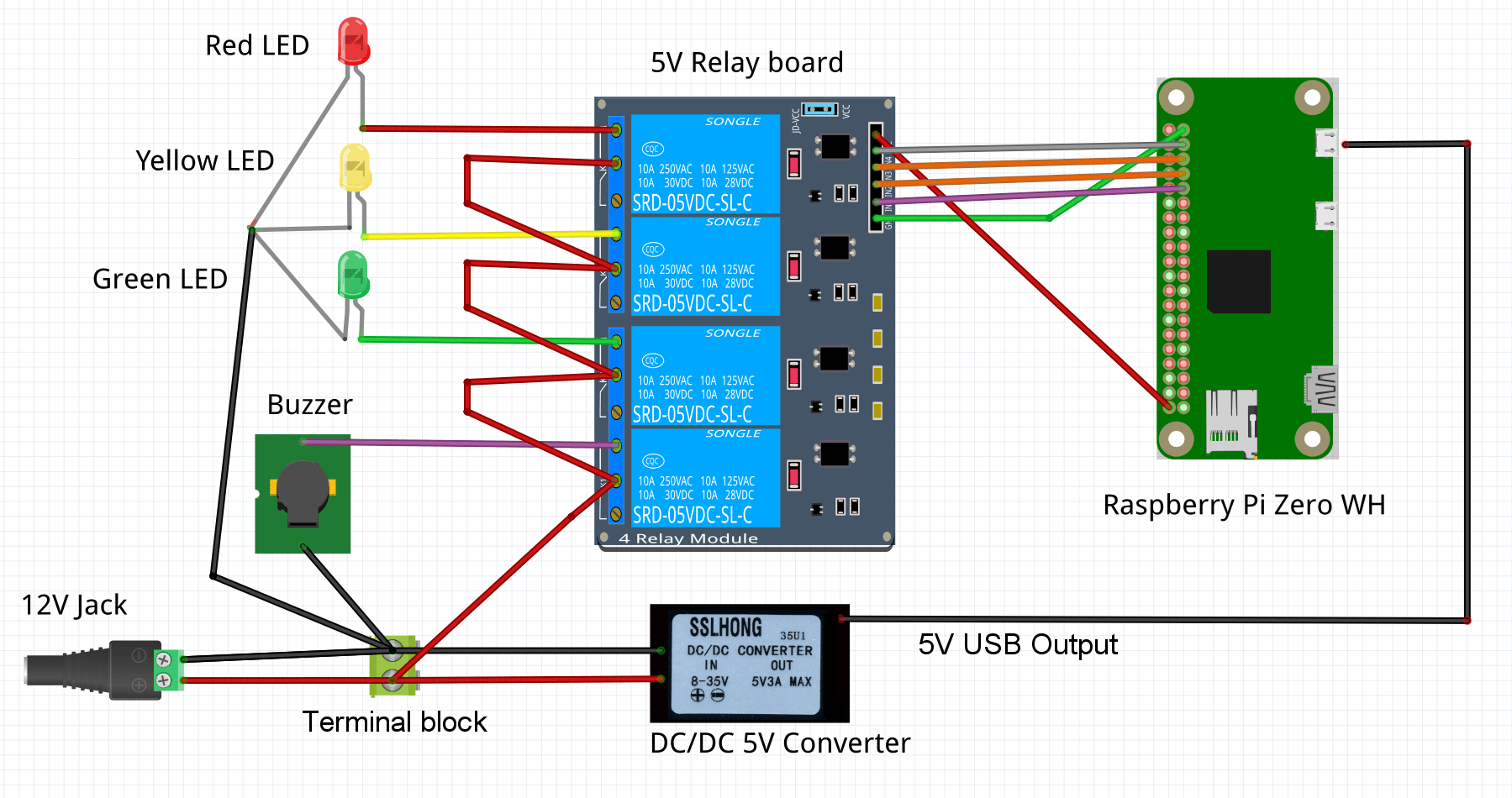
Using the wiring diagram above as an overall guide, first make the connections between your Raspberry Pi pins and relay board. (If you have a relay HAT, you merely need to attach the HAT instead) The easiest way to make these connections is with female-to-female “breadboard jumper wires” (also known as dupont wires or jumper jerky.) They are frequently sold in strips of 40 but are very easy to peel apart to provide just the number of leads you need.

Here is a summary of the wiring that needs to be made between the pins on the relay board and and the pins on the Pi:
| Relay Board Pin | Raspberry Pi Pin (except RPi 1A or 1B) | Raspberry Pi 1A or 1B Pin |
|---|---|---|
| GND | Pin 39 (ground) | Pin 25 (ground) |
| IN1 | Pin 31 (GPIO6) | Pin 15 (GPIO22) |
| IN2 | Pin 33 (GPIO13) | Pin 19 (GPIO10) |
| IN3 | Pin 35 (GPIO19) | Pin 21 (GPIO9) |
| IN4 | Pin 37 (GPIO26) | Pin 23 (GPIO11) |
| VCC | Pin 2 (5V) | Pin 2 (5V) |
Next, connect your LEDs to the relay board. The positive leads from the LEDs connect to the normally open (N.O.) terminals on the relay board. All of the negative leads should be connected together. If you are using the LED tower, all of the negative leads have already been connected together inside the tower, and only that common wire needs to be connected to your -12V jack or terminal block. If you have a buzzer, connect that to the remaining relay.
Now connect the positive lead from your 12V power supply jack to the middle position on each relay. You could connect all of the center relay terminals together or wire each one to the positive +12V supply separately.

Finally, connect the power converter’s 12V leads to your 12V power terminals or jack. The 5V wire coming from the converter should be connected to the power jack on the Raspberry Pi. If your converter does not have a micro USB output, attach the proper adapter first.
Tinkerer build diagram
If you’re doing the tinkerer build, you might find value in this diagram (though your mileage may vary, hacker).
Your project should now be wired and ready to go; make one last check against the diagram, but don’t plug in the power supply just yet.
Set up the software
The balenaCloud platform will take care of providing a lightweight OS for your device as well as deploying the web application so just follow along with the steps below on your development computer (not on your Raspberry Pi). Follow these steps regardless of whether you assembled the elaborate tower or are using an LED HAT.
Sign up for a free balenaCloud account
The first 10 devices are free so you could create a small fleet of LED Alerters. Sign up here.
Create a balenaCloud application
Once you are inside your balenaCloud account, click the “Create application” button in the upper left and give your application a unique name and select the appropriate device type.
Add a device and download the balenaOS disk image from the dashboard
Now that you’ve created your application, you’re ready to add a device. Click the “+ Add device” button in the upper left part of the interface and use the following guidelines to make your selections:
- Select the model of your Raspberry Pi
- Use the recommended build version of balenaOS
- Select the “Development” edition of the recommended balenaOS. To learn about the differences between the development and production editions, see this page.
- If you plan to connect your Raspberry Pi to a WiFi connection, enter your WiFi username and password details. It’s a good idea to enter your WiFi network details even if you initially only plan on connecting via Ethernet, as it will save time if you wish to switch to WiFi in the future.
Once you select your configuration options, click on the “Download balenaOS” button to start downloading a custom balenaOS disk image to your desktop. This image is built specifically to connect your device to the application you just created.
Flash your SD card with the balenaOS disk image
After you have successfully downloaded the balenaOS disk image, you now need to flash this disk image to your SD card. Balena’s very own balenaEtcher is a great free tool for this purpose.
To flash your SD card, connect your SD card to your computer via an internal or external SD reader/writer drive. Open balenaEtcher, select the balenaOS disk image you just downloaded, and select your connected SD card as the destination drive. Next, click “Flash” to write the disk image onto your SD card. This writing process can take several minutes. Be patient!
If you’ve thoroughly checked your wiring and are confident that everything is correct, go ahead and plug in the power supply. The device should boot up with the balenaOS operating system and then show as “online” in the balenaCloud dashboard.
Install the balena CLI tools on your workstation
The balena CLI tools are used to send the project code to your device, if you’ve already built any of our other projects you’ll probably have them installed already. If not there are standalone binaries and installers for Windows, macOS, and Linux available. If you already have npm on your machine, use the balena-cli npm package to get the CLI tools up and running quickly.
For more information, the documentation for the CLI tools is the best place to start, and covers the installation and setup of both the npm package and the standalone binaries.
When you have the CLI installed and working, the first step is to login to balenaCloud by issuing the balena login command in the command prompt. (To access the command prompt in Windows, search for cmd in the “Type here to search” box near the start button.)

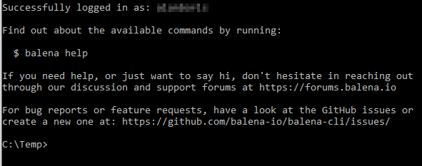
Once you’ve reached this point, and have a working CLI which has been logged in to your account, you’re ready to start pushing code to your Raspberry Pi.
Downloading the project from Github
Download the code for this project from this repository.
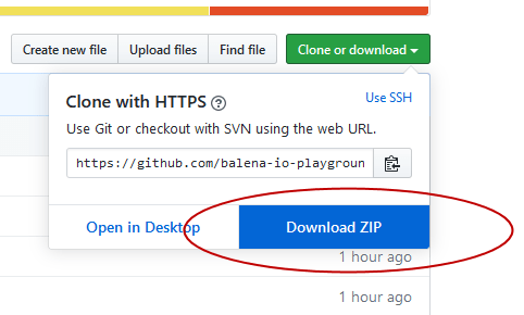
The blue button will download a .zip file of the project which you’ll need to unzip, but if you’re already familiar with Git you can use git clone instead.
Pushing the project code to your Raspberry Pi
Since you have the CLI set up and the latest code downloaded, you can now execute a single command to push that code to balenaCloud which in turn builds the Docker image and handles the process of setting it up and running it on your device.
From within the unzipped project directory (use cd to change directories), execute balena push <appName>, where appName is the application name you set back at the beginning of the guide. For example: balena push led-alerter.
Usage and Configuration
If you followed the wiring diagram and “elaborate” build steps above, you should see the green LED light up a few minutes after you push the code. If not, go ahead and re-check all of your connections and software setup steps.
If you used an LED HAT or different GPIO pins than the ones in the instructions, (or a Raspberry Pi 1A or 1B) you’ll need to set a few device variables in the balenaCloud dashboard. This feature of balenaCloud frees us from having to edit any code or configuration files on the device.
To set device variables, first click on the “D(x) Device Variables” block on the left side of the dashboard. Then click the “+ Add variable” button to open the Add variable window.
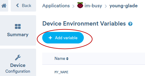
In the “Add variable” window, you can add one variable and its value at a time. Click “Add” after each variable and then repeat the steps to add as many of the variables that apply to your setup. Note that each time you add or change a variable, the application will restart and then apply the new value.

If you used different GPIO pins than the default ones below, you’ll need to add the specified device variable and value. Note: It’s likely that any HAT will not use these default values.
| Variable Name | Description | Default Value |
|---|---|---|
| “LED_RED_GPIO” | GPIO # used for red LED | 26 |
| “LED_YELLOW_GPIO” | GPIO # used for yellow LED | 19 |
| “LED_GREEN_GPIO” | GPIO # used for green LED | 13 |
| “LED_BUZZ_GPIO” | GPIO # used for the buzzer | 6 |
Another important device variable has to do with the type of output state that your relay board or HAT uses to turn on the LEDs. The popular relay board specified in the parts list has a somewhat reversed logic, where a “high” state actually turns off the LEDs. This is the default value in the software but you can easily change it by setting the LED_RELAY_HIGH variable to a value of 1. If your LEDs act the opposite of what you expect or more than one turns on simultaneously, it is a safe bet you need to set this variable. If you need to revert back to the default logic, set the variable to 0 or delete it.
Now that you’ve set any required variables, it’s time to access the web page hosted on your device that will allow you to control the LEDs. Let’s just clarify that the LED Alerter page lives on your device and is used to control the LEDs for that device. This is in contrast to the balenaCloud dashboard pages which are hosted by balena and allow you to monitor and make changes to your device configuration via the cloud.
On the balenaCloud dashboard, find your device’s local IP address and click the icon next to it to copy to your clipboard. Paste that into another browser window to access the device’s LED Alerter web page.

If you want to instantly access your LED Alerter page from anywhere in the world, enable the “Public Device URL” (right under the IP address) and click the icon next to that to open it in another browser window. The device URL is listed in the address bar of the browser window.
You can customize the look of your LED Alerter web page by setting the following device variables:
| Device variable name | Description | Default value if not set |
|---|---|---|
| “LED_MY_NAME” | Name of device displayed above the buttons | Device name on dashboard (which you can change using the pencil icon) |
| “LED_RED_LABEL” | Label on red button | red |
| “LED_YELLOW_LABEL” | Label on yellow button | yellow |
| “LED_GREEN_LABEL” | Label on green button | green |
A button will display “(On!)” if that color LED is currently lit. This can be useful when multiple people are using the same LED Alerter webpage to control the LEDs. The on/off status will update in real time.
How it works
The software on the device is written in Node.js, a JavaScript runtime. The npm onoff package is used to control the GPIO pins in conjunction with a small Express web server that serves the LED Alerter web page. We’re using a WebSocket server to create a persistent connection between the client and server, each of which is responding to various events. In our example, the webpage is the client, and when one of its buttons is clicked, it sends an event to the server, which turns on the appropriate LED. In addition, when the server changes the LED status it emits an event that the web page client responds to and updates the button text.
Taking it further
The LED Alerter can be enhanced with many features to make it even more useful for letting others know when you are busy or don’t want to be disturbed. It could be synced to a calendar for automatic operation. Another possibility is to link it with e-mail or chat to trigger LED changes. The project is fully open source and we welcome any contributions from the community to help improve it; no matter if it’s submitting a bug report, a feature request or even a PR with new code. The balenaCloud platform is optimized for fleet operations, so having one Alerter control many devices or controlling many devices with one Alerter would be an interesting feature to implement.
This project is a great example of an IoT device that outputs data rather than the typical task of collecting data from sensors. Since the device uses relays to control the output, you are not limited to turning on and off LEDs. Most relays can handle higher current and voltages so you could conceivably turn on or off much larger lights or appliances.
Let us know if you’re building this project and what you can think of! We’re always interested in chatting on Twitter, Facebook, and our Forums.