
We’ve covered a couple of ways to build a LoRa gateway for The Things Stack (TTS) here on the blog and on YouTube, but what about if you want to take advantage of your own gateway and deploy some sensors in your home or garden?
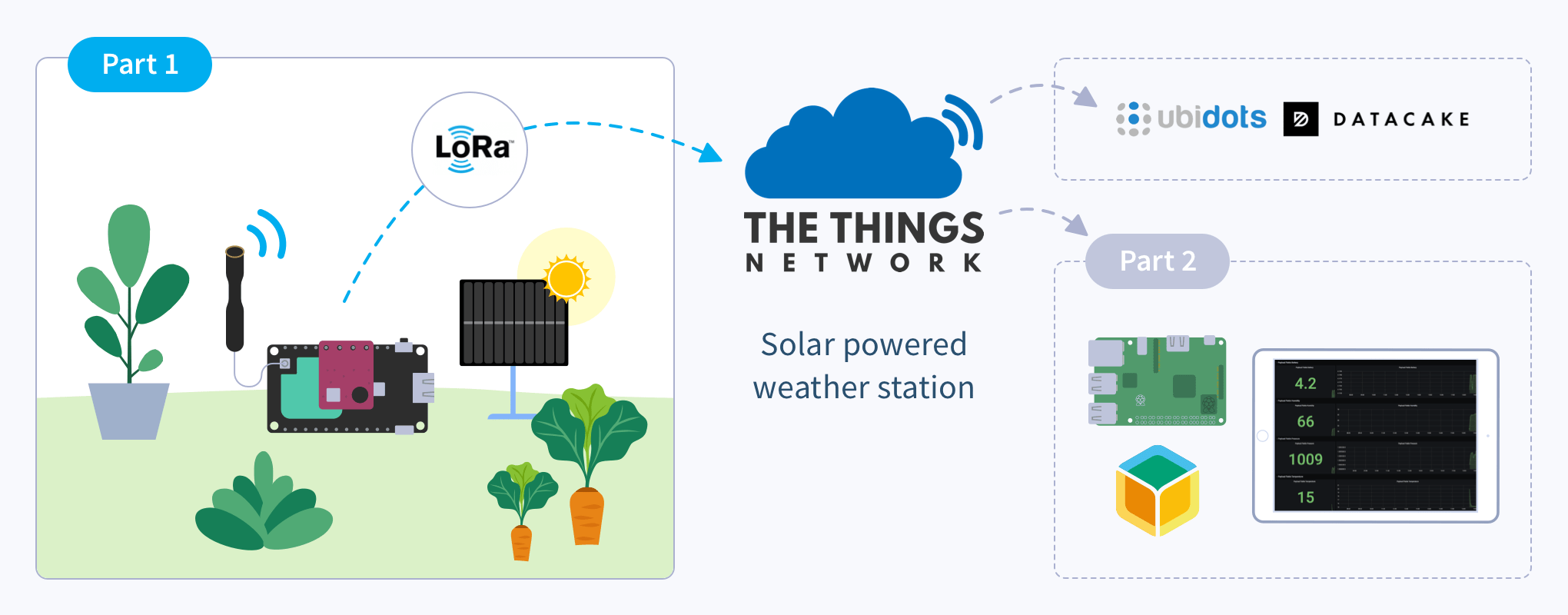
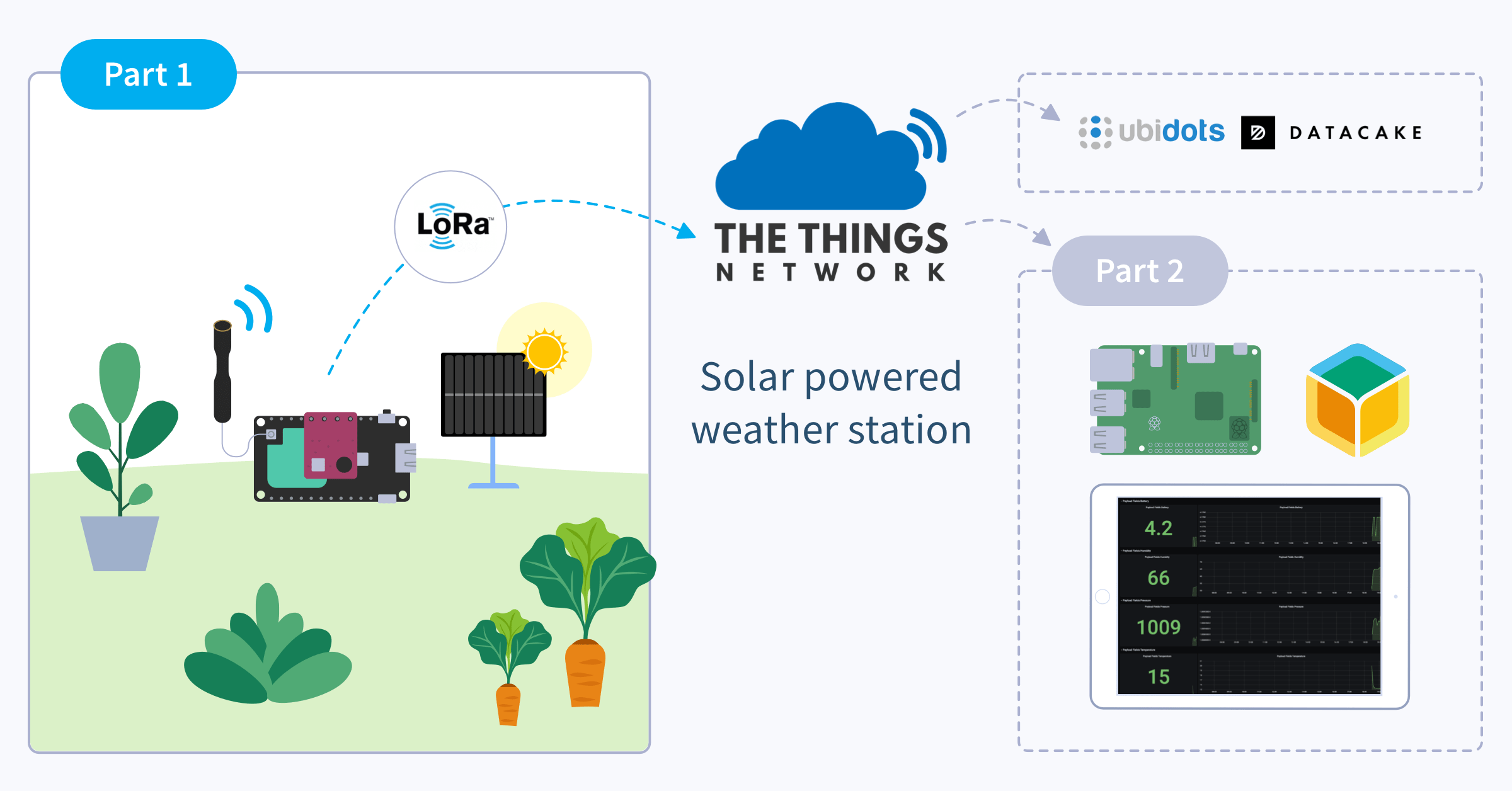
This two-part series will explore how to build a simple, solar-powered weather station, and in the second part, set up a way to receive the data! Let’s hit this.
NOTE 28th June 2021: The Things Network (TTN) is moving officially to The Things Stack (TTS). TTN is no longer available to create LoRaWAN gateways, so we’ve adjusted this guide to reflect this change.
Before we begin
Introduction
So, you’ve got your TTS gateway up and running, or perhaps you’ve checked the map and noticed that handily you’re already in range of an existing gateway. Now you can start to utilize the network coverage provided by these gateways to deploy very low powered devices that are able to run for years on a single charge or perhaps indefinitely with the addition of a solar panel and some sunlight.
In this post we’re going to focus upon building a very simple LoRa node device that will take temperature, humidity and pressure readings. The data will flow from the LoRa node, to TTS (via a gateway), where it can then be passed on to another device for storage and reporting. Depending on the positioning of both your gateway (or the nearest gateway to you) and your sensor, a distance of 10km (6 miles) should be no problem, sometimes LoRa devices can be used to transmit for 100s of kilometers! LoRa is a great way to connect sensors like this as it’s both low-power and long range.
Hardware required
The parts to build this sensor should be around $20-25 US (£15-20 GBP) depending on where you get them from. I’ve included AliExpress links below as they tend to ship globally but sometimes you can have better luck shopping with suppliers local to you.
- Bosch BME280 breakout board (AliExpress – I chose these because the pinout exactly matches that of the dev board enabling you to solder it straight on)
- Heltec CubeCell HTCC-AB01 (AliExpress – be sure to select the correct LoRa frequency for your country)
- 3.7V LiPo cell (I’m using a 650mAh one) with a micro JST (1.25mm pitch) connector
- Optional: 6V 110x60mm solar panel (AliExpress)
- Optional: 3D printed housing and associated hardware
Software required
- Arduino IDE
- SiLabs CP2104 Driver (installation instructions)
- CubeCell framework added to Arduino IDE (installation instructions)
- Seeed Studio BME280 Library added to Arduino IDE
- A free TTS account (register here)
Setting up The Things Stack
Step 1: Create an application
Once you have your TTS account registered and logged in, the next step is to create an application. The application will be home to the node devices and allow us to capture data from them and send them to our chosen endpoint (later on in the guide).
Find the Applications tab within your account, and follow the user interface to add one.
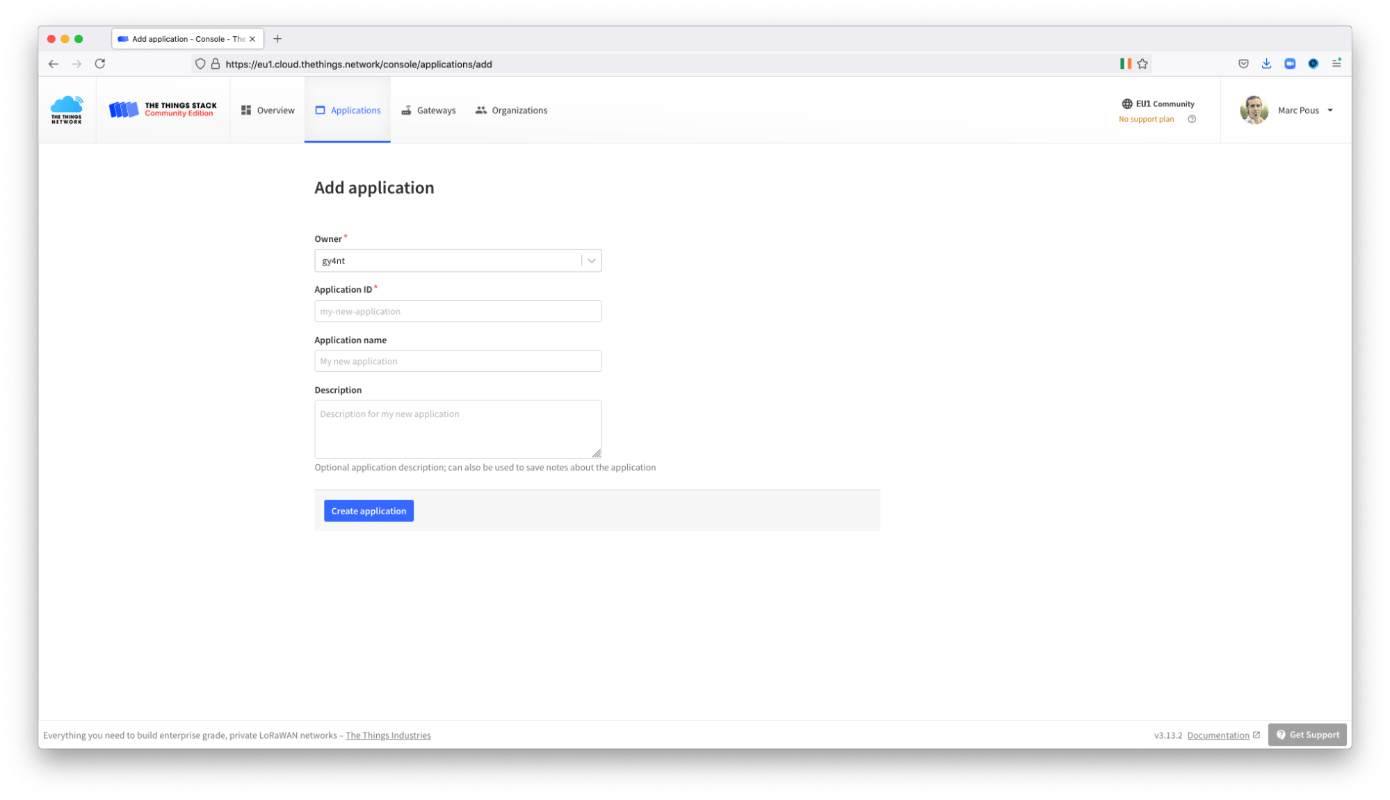
Fill the form, giving an application ID and description of your choosing. Select the handler closest to your physical location from the dropdown list, and click ‘Create application.’
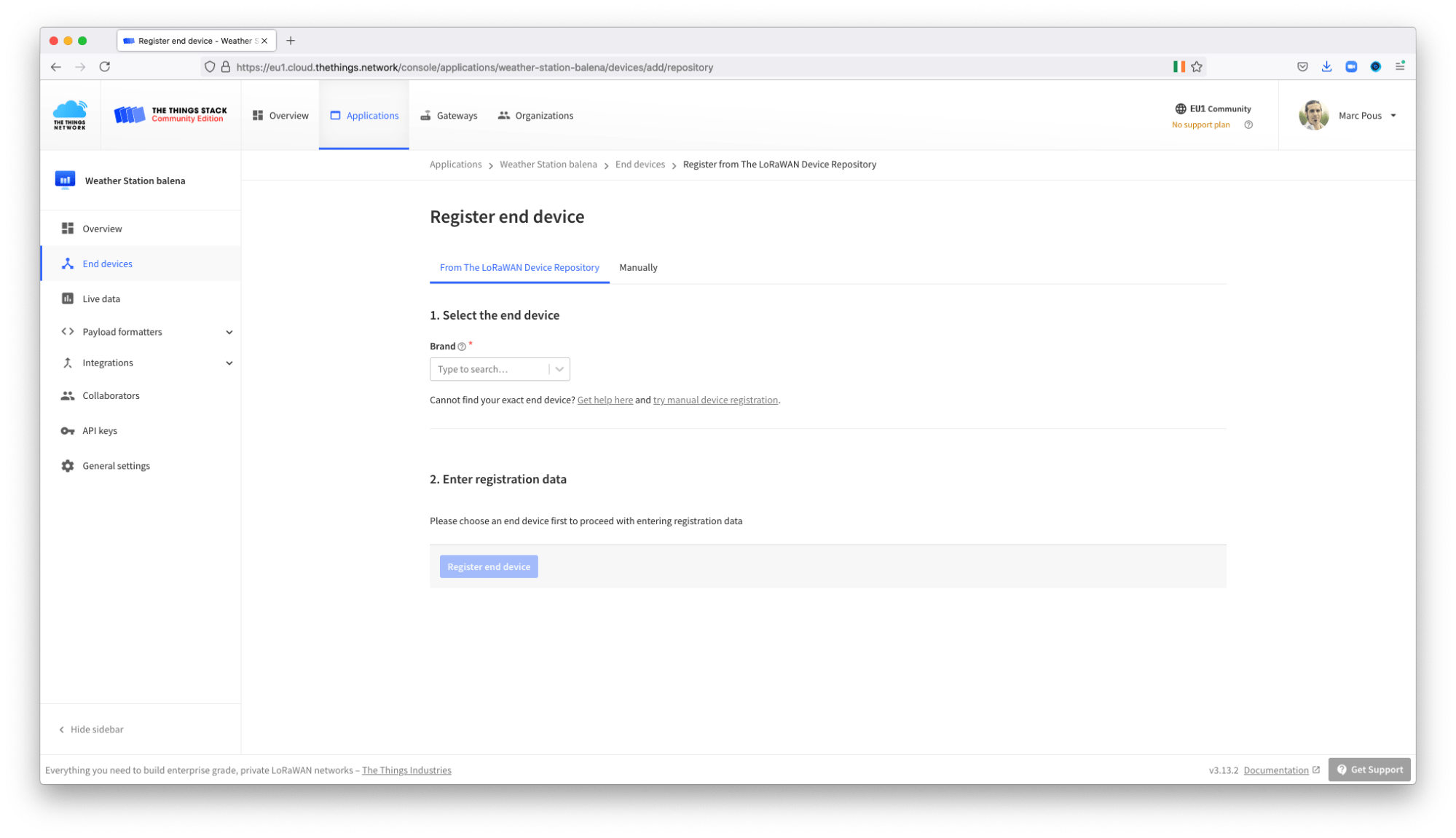
Step 2: Register a device
Next, find devices within your newly created application and select ‘Add end device’. This will allow us to register a device and generate an identifier and key which we’ll then use later when we flash the node.
For the brand, select Heltec Automation and the model (in case you are using the same device), HTTC-AB01 (Class A OTAA). The frequency to select depends on where you are based.
Ensure that both ‘Device EUI’ and ‘App Key’ are set to be generated by clicking the button to the right of the input box. Otherwise, you’ll have to specify them manually. In general, DevEUI should be provided by the manufacturer, but now, you will need to introduce a random number.
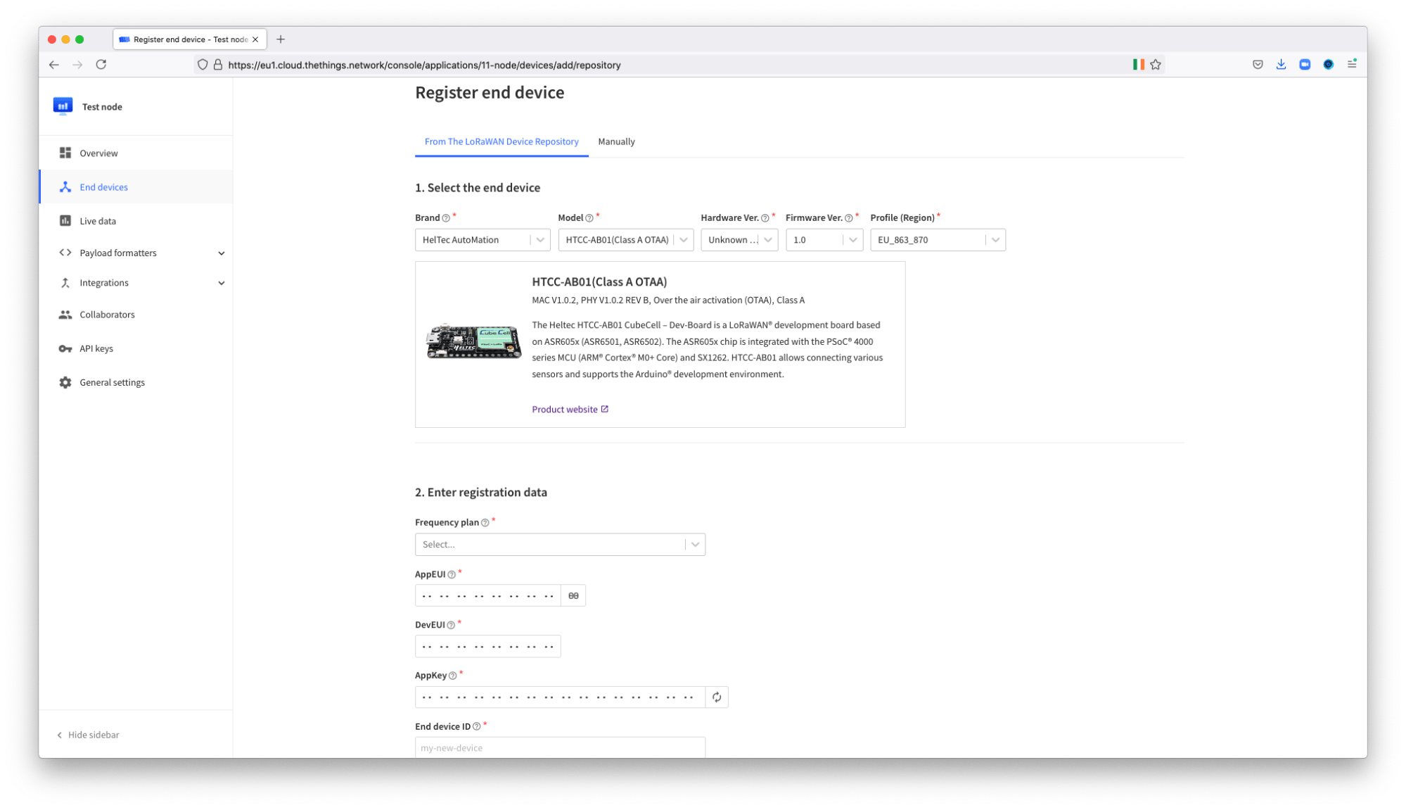
After you’ve clicked ‘Register’, and the device has been created, go to the detail page for the new device you’ve created; here you’ll find values for ‘Device EUI’, ‘Application EUI’ and ‘App Key’. You’ll need these for the next step so either make a note now or remember where they are so you can come back to them later.
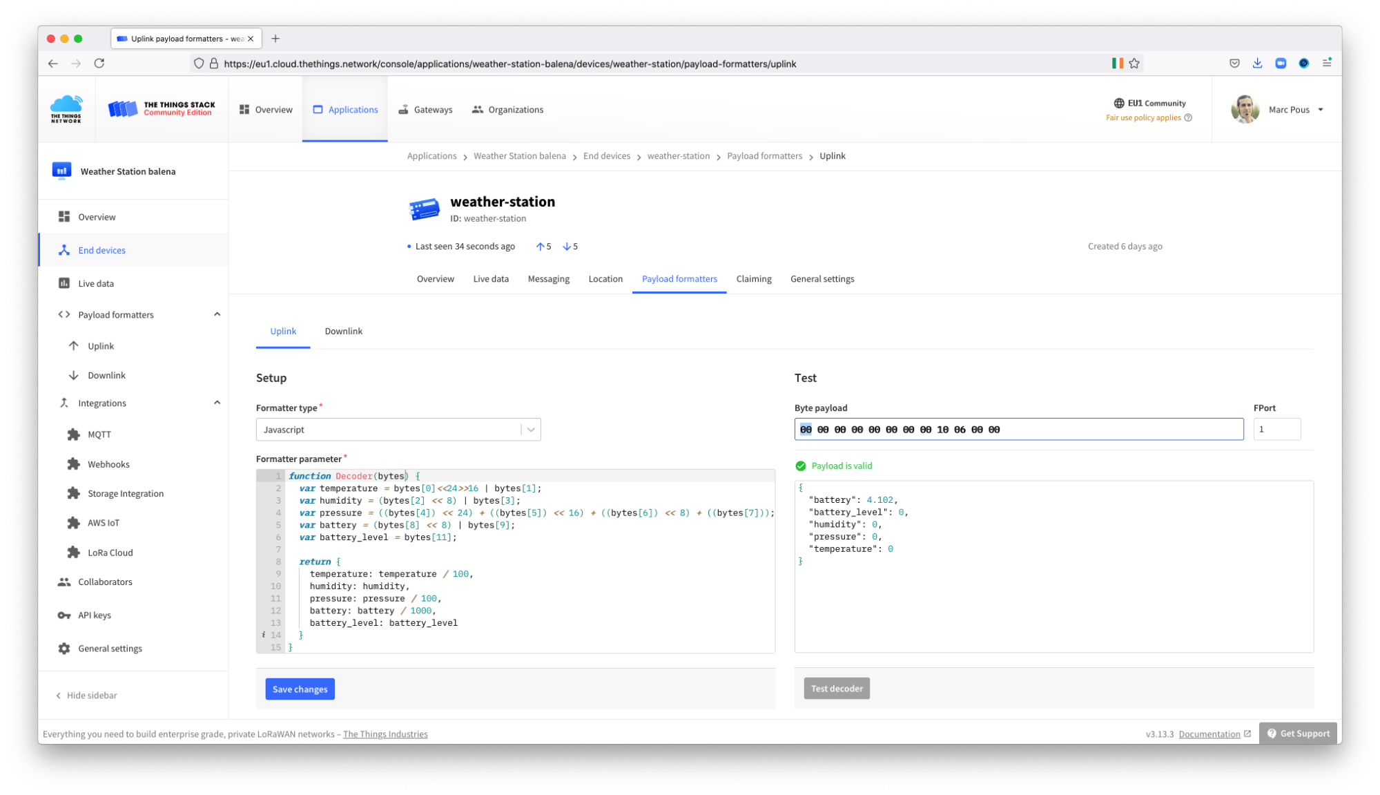
Step 3: Setup the payload decoder
When our device reads values from the attached sensor and sends data to TTS, it’s encoded in a specific way in order to be transmitted via LoRa. When the data arrives at TTS, we can configure the application such that it knows how to decode this data and extract the sensor values.
To set this up, go to the ‘Payload formatters’ section within your TTS application and add the code from the payload-decode.txt file on GitHub.
Electronic assembly & flashing
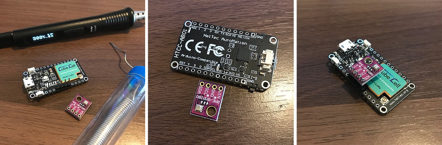
We’re using the Heltec CubeCell HTCC-AB01 dev board for this project, since it’s a relatively cheap way to get up and running with LoRa nodes. We’ll connect the BME280 sensor and then flash the board with the project firmware.
Step 1: Solder the BME280 board to the CubeCell board
Firstly, let’s connect the BME280 sensor board to the CubeCell board. The handy thing about the two boards is that the pins are correctly aligned so that you can simply connect one to the other with a pin header; no wiring required.
We connect SDA -> SDA, SCL -> SCL, GND -> GND and VIN -> Ve. The Ve pin on the CubeCell board is a 3.3V output that is controlled via software, so we can disable power to the sensor when we’re not using it in order to reduce overall power consumption.
Step 2: Ensure you have all the prerequisites installed and running
For this project, as mentioned above under the Software required section, you’ll need to install a few software components on your development computer. Namely the Arduino IDE, the SiLabs CP2104 Driver (installation instructions) must be installed and the CubeCell framework must be added to Arduino IDE (installation instructions).
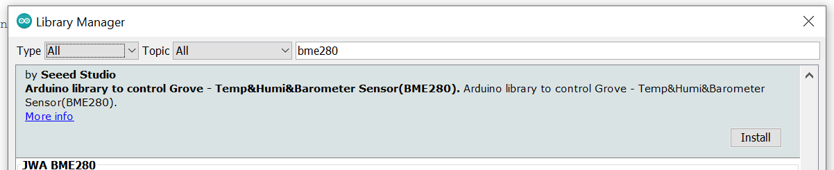
Remember to install the Seeed Studio BME280 sensor library from Tools > Manage Libraries within the Arduino IDE (shown below). Although we’re not specifically using a Seeed sensor, their library does the trick for our BME280 simply and easily.
Step 3: Download and open the project
The code for this project is available on GitHub. Download or clone this repository, extract the .zip file (if applicable), and open the project within the Arduino IDE; this is done by opening the mini-lora-weatherstation.ino file.
Step 4: Connect the board and configure the IDE
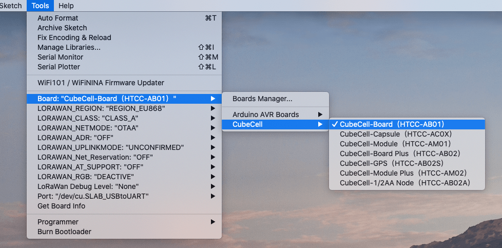
Once you have the project open within the Arduino IDE, make sure the correct board is selected as per the screenshot below. You’ll note there are several configurable options. Pictured are my recommendations; for example disabling the RGB to save power, but you’ll also need to change the LORAWAN_REGION parameter to something appropriate for your location. My board is operating in the UK so I selected REGION_EU868, which also matches the operating frequency of my gateway.
Pay extra attention to the ‘Port’ option, as this may vary depending on your computer operating system and configuration. The easiest way to find the correct one here is to check what options the menu has without the board connected to your computer, plug it in, then check the menu again to see what option appeared when the board was connected.
Step 5: Update the ttnparams.h file
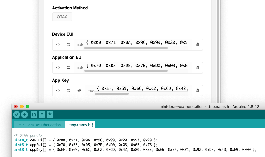
Remember those values we saw on the device page earlier on? Now we need to add them to the application before it’s flashed to the CubeCell board, so that the device will know the credentials with which to transmit the data.
Note the < > button within the TTS console can be used to change the format of the data so that you can copy and paste it into the ttnparams.h file, replacing what was there. After this you should be left with something like the below.
Step 6: Check the Duty Cycle and flash the device
By default, the code will take a reading from the sensor every five minutes, transmit it via LoRa and spend the rest of the time in deep sleep. You can change the frequency of these readings on line 8 of the main mini-lora-weatherstation file, bearing in mind that the more frequent the reading, the higher the overall power consumption of the device will be.
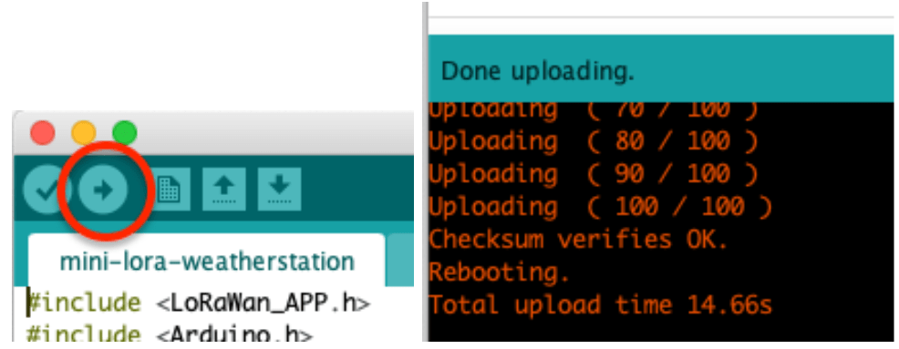
After that, with the board connected to your computer via USB, you can go ahead and click the upload button to compile the firmware with your alterations and flash the device.
Step 7: Test!
If everything up to this point has worked correctly, and your gateway is up and running (or you’re within range of another gateway), then you should start to see data flowing in via the TTS console. Remember to connect the antenna to the board, as your range is likely to be severely limited without that.
Go to your application, and then to the ‘Data’ section, and you should see an initial line with a lightning bolt on the left which is the device registering with the network, and then a second line which has the data from the sensor on the right hand side.
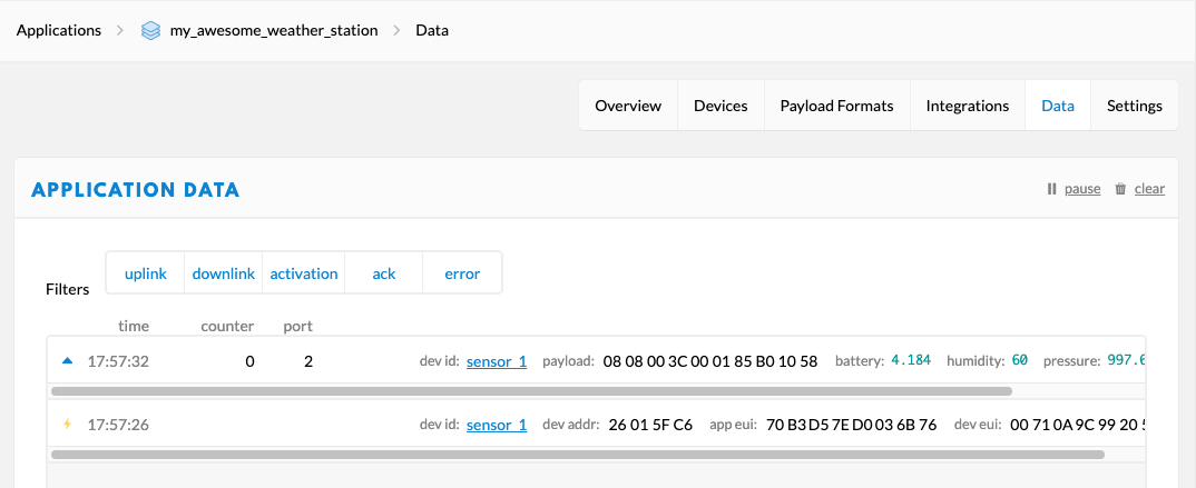
Note that the data console only shows data received from the device whilst the page was open. If you’re not seeing anything, click the reset button on the CubeCell board and the device will reboot and authenticate with the network again causing the two lines to appear.
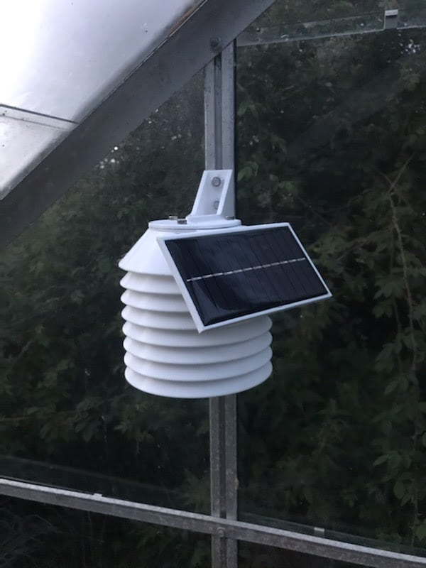
Optional: Solar Panel
A great feature of the CubeCell board is the ability to connect a small solar panel; the board has onboard battery management and will charge the battery from the energy provided by the solar panel.
In my installation, I used this panel, which is 110x60mm panel. I find this, coupled with a 650mAh battery, to provide more than enough power to continuously run the board even during a UK winter where there isn’t always direct sunlight available. If you live in a sunny climate, you can most likely get away with a smaller panel (e.g. a 60x60mm). Make sure the output voltage is still 6V as expected by the CubeCell board.
The solar panel can be connected to the pins marked Vs and GND on the board. I connected mine via a 2-pin header so that I was able to disconnect it in the event that I needed to dismantle the case.
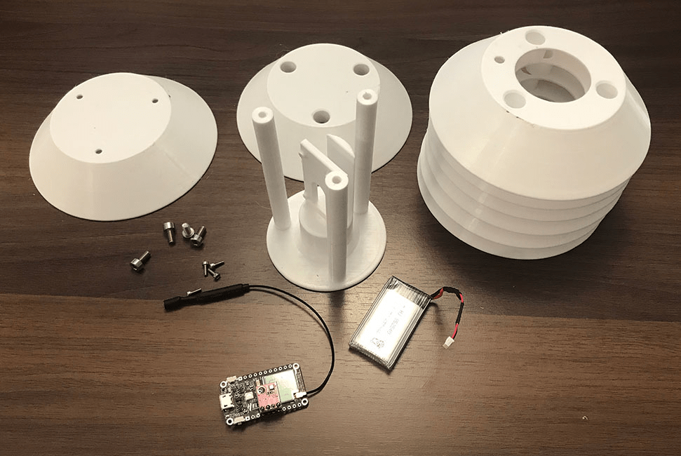
Printing & assembling the case
We’ve designed a case to house the CubeCell board with the BME280 attached along with a 3.7V ~650mAh lithium battery. All of the .STL files for printing the case are within the housing directory on GitHub, along with the .STEP files should you wish to make any modifications (PRs welcome!).
For a complete case you’ll need to print:
- 1x Base (mini-lora-ws-base.stl)
- 6x Open layers (mini-lora-ws-openlayer.stl)
- 1x Closed layer (mini-lora-ws-closedlayer.stl)
- 1x Top layer (mini-lora-ws-top.stl)
- Optional: 1x Solar panel bracket
The holes in the top of the posts and in the upright stand for the CubeCell board on the base are tapping size for M4 and M2 respectively. This means that after it is printed you can run a standard tap into the hole and get some quality threads.

Once you’ve printed the parts they should fit together – tolerances should be large enough to cater for minor variations in prints but you may need to clean up the edges of the holes in the layers if your first layer is a bit squashed.
If you’re adding a solar panel that layer can be placed between the top layer and the bracket.
What next?
At this point you should be up and running with your LoRa node and be able to see the data coming into the TTS console. Once that data arrives with TTS it is then discarded, because we have yet to set up a destination for it.
In the second part of this series we’re going to set up a Raspberry Pi to receive the data from TTS, store it in a database and present it with a nice dashboard. If you don’t want to set up your own device to receive data, there are several cloud providers that you can set up; we like both Ubidots and Datacake.
If you’ve successfully built your weather station and you’re up and running, we’d love to hear about it! Tweet us, tag us on Instagram, or hit us up on Facebook. Similarly, if you had any problems, get in touch with us on the forums and we’d be glad to help out.
Hello @reivis welcome to the balena forums! And happy to see you interested on trying this project!
I’m sure you can use it on Cayenne. I see several possibilities:
Does it make sense to you? Let us know if we can help you more
Hello, thank you for presenting this interesting project. Certainly a beginner’s question: Could additional sensors be integrated? For example one (or more) DS18b20, (or soil moisture sensor)? Can you even have 2 libraries for temperature? And if so, how?
Hello @J_Paul welcome to the balena forums
I’m not an expert on the
Heltec Cubecelldevices but i’m sure that you can find examples, such as this one here.Let us know if that works!
Hello @reivis did you adapt the code to something like this? CayenneLPP | The Things Network
let me know what errors do you get!
@reivis could you please share your Arduino code?
#include <LoRaWan_APP.h>
#include <Arduino.h>
#include <Seeed_BME280.h>
#include <Wire.h>
#include “ttnparams.h”
bool ENABLE_SERIAL = false; // enable serial debug output here if required
uint32_t appTxDutyCycle = 1200000; // the frequency of readings, in milliseconds(set 300s)
uint16_t userChannelsMask[6]={ 0x00FF,0x0000,0x0000,0x0000,0x0000,0x0000 };
LoRaMacRegion_t loraWanRegion = ACTIVE_REGION;
DeviceClass_t loraWanClass = LORAWAN_CLASS;
bool overTheAirActivation = LORAWAN_NETMODE;
bool loraWanAdr = LORAWAN_ADR;
bool keepNet = LORAWAN_NET_RESERVE;
bool isTxConfirmed = LORAWAN_UPLINKMODE;
uint8_t appPort = 2;
uint8_t confirmedNbTrials = 4;
int temperature, humidity, batteryVoltage, batteryLevel;
long pressure;
BME280 bme280;
static void prepareTxFrame( uint8_t port )
{
// This enables the output to power the sensor
pinMode(Vext, OUTPUT);
digitalWrite(Vext, LOW);
delay(500);
if(!bme280.init()){
if(ENABLE_SERIAL){
Serial.println(“Device error!”);
}
}
// This delay is required to allow the sensor time to init
delay(500);
temperature = bme280.getTemperature() * 100;
humidity = bme280.getHumidity();
pressure = bme280.getPressure();
Wire.end();
// Turn the power to the sensor off again
digitalWrite(Vext, HIGH);
batteryVoltage = getBatteryVoltage();
batteryLevel = (BoardGetBatteryLevel() / 254) * 100;
appDataSize = 12;
appData[0] = highByte(temperature);
appData[1] = lowByte(temperature);
appData[2] = highByte(humidity);
appData[3] = lowByte(humidity);
appData[4] = (byte) ((pressure & 0xFF000000) >> 24 );
appData[5] = (byte) ((pressure & 0x00FF0000) >> 16 );
appData[6] = (byte) ((pressure & 0x0000FF00) >> 8 );
appData[7] = (byte) ((pressure & 0X000000FF) );
appData[8] = highByte(batteryVoltage);
appData[9] = lowByte(batteryVoltage);
appData[10] = highByte(batteryLevel);
appData[11] = lowByte(batteryLevel);
if(ENABLE_SERIAL){
Serial.print(“Temperature: “);
Serial.print(temperature / 100);
Serial.print(“C, Humidity: “);
Serial.print(humidity);
Serial.print(”%, Pressure: “);
Serial.print(pressure / 100);
Serial.print(” mbar, Battery Voltage: “);
Serial.print(batteryVoltage);
Serial.print(” mV, Battery Level: “);
Serial.print(batteryLevel);
Serial.println(” %”);
}
}
void setup()
{
boardInitMcu();
if(ENABLE_SERIAL){
Serial.begin(115200);
}
deviceState = DEVICE_STATE_INIT;
LoRaWAN.ifskipjoin();
}
void loop()
{
switch( deviceState )
{
case DEVICE_STATE_INIT:
{
printDevParam();
LoRaWAN.init(loraWanClass,loraWanRegion);
deviceState = DEVICE_STATE_JOIN;
break;
}
case DEVICE_STATE_JOIN:
{
LoRaWAN.join();
break;
}
case DEVICE_STATE_SEND:
{
prepareTxFrame( appPort );
LoRaWAN.send();
deviceState = DEVICE_STATE_CYCLE;
break;
}
case DEVICE_STATE_CYCLE:
{
// Schedule next packet transmission
txDutyCycleTime = appTxDutyCycle + randr( 0, APP_TX_DUTYCYCLE_RND );
LoRaWAN.cycle(txDutyCycleTime);
deviceState = DEVICE_STATE_SLEEP;
break;
}
case DEVICE_STATE_SLEEP:
{
LoRaWAN.sleep();
break;
}
default:
{
deviceState = DEVICE_STATE_INIT;
break;
}
}
}
Hello @reivis you should add the Cayenne Library (Cayenne LPP). More information here CayenneLPP | The Things Stack for LoRaWAN
Here you have an example Cayenne_encoding – #20 by naidu.hemanth9 – Helped – myDevices Cayenne Community
And here more information about the Cayenne Payload Cayenne Docs
Hi,
I have just a quick question. I have successfully built a weather station according to this guide. Working fine so far. I just stumbled over the battery level. It just shows 0 or 1 (when fully loaded) but is supposed to show a percentage …
I did not alter anything at the script nor the payload… Any hints?
Hello @fhansi welcome to the balena.io community!
could you please confirm the value when the battery it’s not fully loaded? i think what is on Grafana is a visualization of the percentage of this value, but i’m not totally sure.
Let me know if this makes sense
@fhansi the source for this information is the firmware on the Heltec board. It’s returned as a value from the
BoardGetBatteryLevel()function, then added to the LoRA packet along with all the other data.You’d have to figure out where it’s getting lost, or even if it’s being reported correctly to begin with. I’d suggest starting with adding some debug lines to the Arduino to print the output to the log. You could also figure out the percentage yourself using the battery voltage levels based on a table like this one: Lipo Voltage Chart: Show the Relationship of Voltage and Capacity – Ampow Blog